
Controllable lightning arrester control switch position judgment system and method

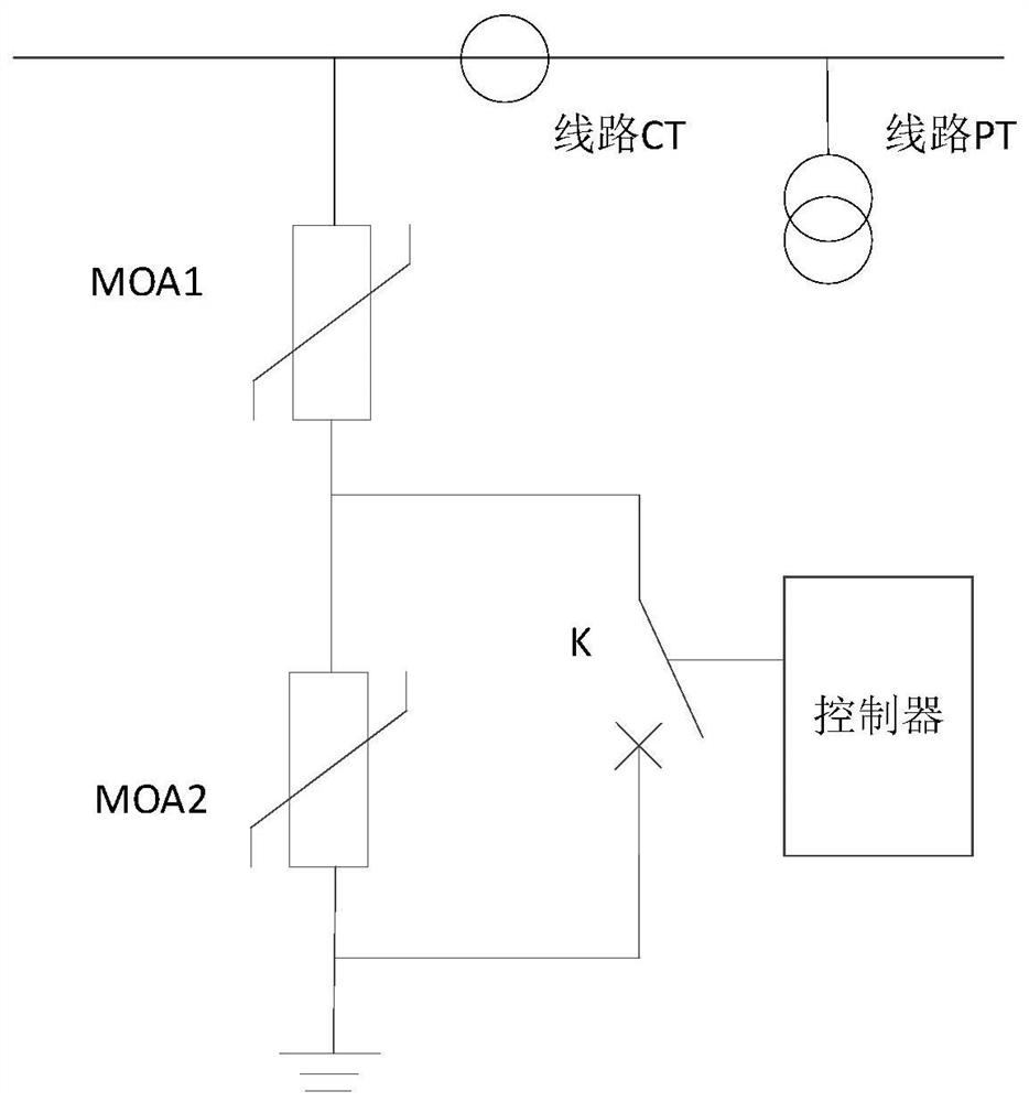
A technology for controlling switches and arresters, which is applied in the field of control switch position judgment systems of controllable arresters, can solve problems such as low acquisition accuracy, small current value, and inability to apply engineering practice, and achieves avoiding serious faults, high judgment accuracy, and improved reliability. sexual effect

Pending Publication Date: 2021-03-26
NR ELECTRIC CO LTD +2
View PDF5 Cites 1 Cited by
  • Summary
  • Abstract
  • Description
  • Claims
  • Application Information

AI Technical Summary

Problems solved by technology

Therefore, it is very important to reliably judge the opening position of the control switch of the controllable arrester. When a misjudgment occurs, it will lead to a serious accident of UHV line tripping.
[0004] There are two methods for traditional switch opening position detection, one is relatively simple, the control system is judged by taking the opening and closing position contacts of the switch, due to the high failure rate of the position contact of the switch, this detection method is not reliable , suitable for medium and low voltage, low importance occasions, not suitable for controllable surge arresters; the other is used in high voltage protection such as circuit breaker failure protection, using branch current criterion, negative sequence, zero sequence current auxiliary judgment , while the controllable arrester is not separated when the line has voltage control switch, the control switch only flows through the leakage current of milliampere level, and the current value is very small; when the arrester operates, it flows a large operating current, and the current transformer is selected Difficult to model, low acquisition accuracy, can not be applied in engineering practice

Method used


Image

  • Controllable lightning arrester control switch position judgment system and method
  • Controllable lightning arrester control switch position judgment system and method
  • Controllable lightning arrester control switch position judgment system and method

Examples


Embodiment 1

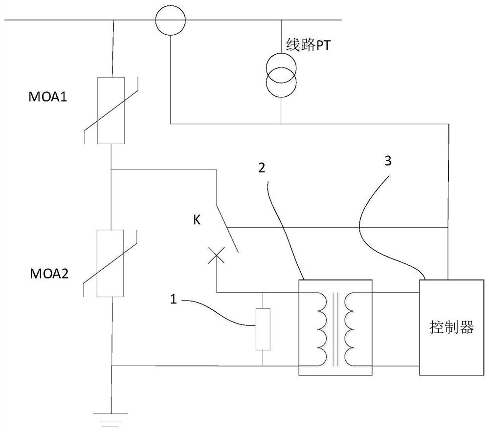
[0048] The invention proposes an embodiment of a control switch position judgment system of a controllable lightning arrester, which includes a sampling resistance element, a voltage isolation converter and a controller. The sampling resistance element is connected in series with the control switch, and then connected in parallel with the controllable part of the arrester; the input terminal of the voltage isolation converter is connected in parallel with the sampling resistance element, and the output end is connected to the controller; the controller collects line voltage, line current, and voltage of the sampling resistance element And the position signal of the control switch to judge the position of the control switch.

Embodiment 2

[0050] figure 2 Shown is another embodiment of the joint judging system for the opening position of the control switch of the controllable arrester of the present invention. The sampling resistance element 1 is connected in series in the control switch circuit, one end is connected to the lower port of the control switch K, and the other end is connected to the controllable part of the arrester. The lower end of MOA2 is connected; the input end of the voltage isolation converter 2 is connected in parallel with both ends of the sampling resistor, and the output end is connected with the controller 3 . The controller 3 collects the voltage of the sampling resistance element 1 through the voltage isolation converter 2, collects the voltage and current of the line through the line PT and the line CT, and simultaneously collects the position contact of the control switch, and judges the position of the control switch through these quantities.

[0051]Through the above method, when...

Embodiment 3

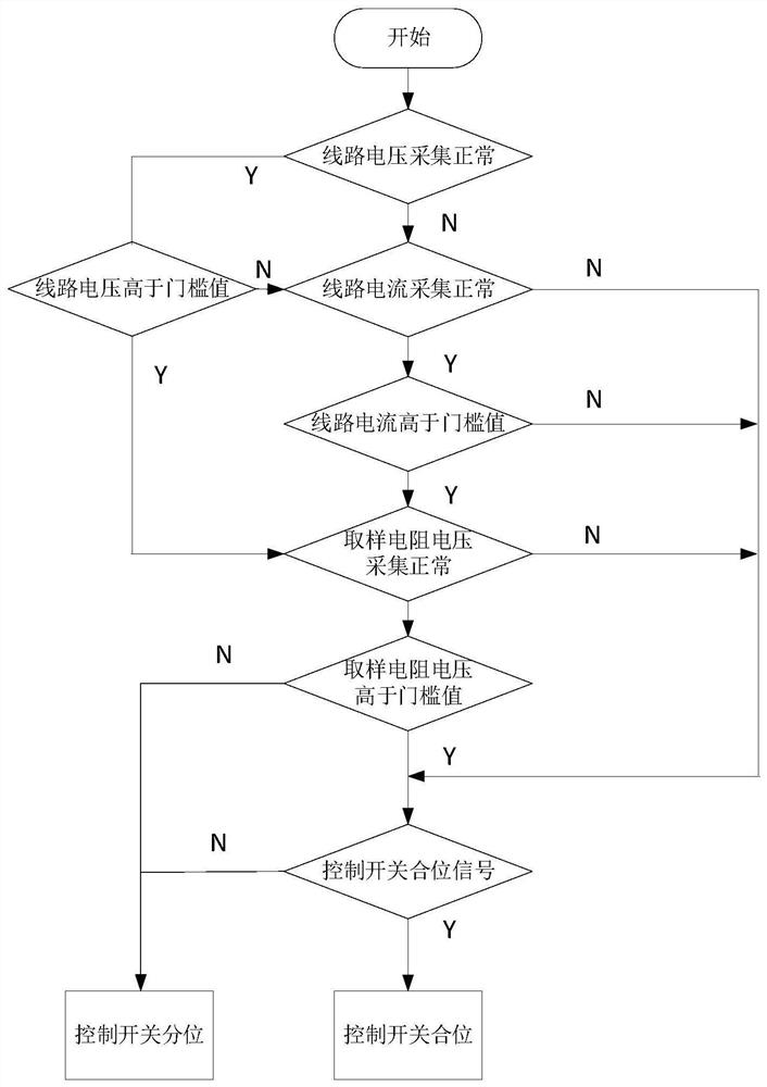
[0054] An embodiment of the judging method of the control switch position judging system of the controllable arrester of the present invention includes: comprehensively judging the control switch position according to the following four criteria.

[0055] Electric quantity criterion one: judge whether the line voltage is higher than the voltage setting threshold 1.

[0056] Electric quantity criterion two: judge whether the line current is higher than the current setting threshold.

[0057] Electric quantity criterion three: judge whether the voltage value of the sampling resistance element is higher than the voltage setting threshold 2; if yes, preliminarily judge that the control switch is in position, otherwise preliminarily judge that the control switch is in position.

[0058] Switch value criterion: control whether the switch position signal is closed or divided.

[0059] When the electrical quantity criterion 1 or the electrical quantity criterion 2 is satisfied, the p...


PUM


Abstract

The invention provides a controllable lightning arrester control switch position judgment system. The system comprises a sampling resistor element, a voltage isolation converter and a controller. Thesampling resistor element is connected in series with the control switch and then connected in parallel with the controllable part of the lightning arrester; the input end of the voltage isolation converter is connected with the sampling resistor in parallel; the controller collects the line voltage, the line current, the sampling resistor voltage and the position signal of the control switch to judge the position of the control switch. The invention also correspondingly provides a method for judging the position of the control switch of the controllable lightning arrester, wherein the line voltage, the line current and the voltage value of the sampling resistor element serve as the electric quantity criterion, while the control switch position signal is used as a switching value criterion, and the judgment of the position of the control switch is comprehensively carried out according to a plurality of criteria. According to the invention, the reliability of judging the position of thecontrol switch of the controllable lightning arrester can be improved, and line switch maloperation caused by switch position contact faults is avoided.

Description

technical field [0001] The invention belongs to the field of high-voltage and extra-high voltage power transmission, and in particular relates to a system and method for judging the position of a control switch of a controllable arrester. Background technique [0002] The controllable surge arrester is an operating overvoltage flexible limiting device that adapts to changes in operating conditions. The arrester body is composed of a controllable part and a fixed part in series. Both ends of the controllable part are connected to the control switch, and the control switch is closed. Exit, the control switch is opened and the controllable part is put into use. [0003] The working principle of the controllable arrester is that when the line has no voltage, the control switch closes to prepare to suppress the overvoltage of closing and reclosing; when the line turns from no voltage to voltage, the control switch opens with a delay. At this time, if the control switch fails to ...

Claims


Application Information

Patent Timeline
Patent Type & Authority Applications(China)
IPC IPC(8): G01R31/327
CPCG01R31/327
Inventor 李志兵张磊赵大翠张春合葛健陈秀娟
Owner NR ELECTRIC CO LTD
Learn More