Glenoid implant

a glenoid and implant technology, applied in joint implants, prostheses, medical science, etc., can solve problems such as premature loosening and breakout torqu

Inactive Publication Date: 2014-05-13
ASTON MEDICAL DEV
View PDF14 Cites 9 Cited by
  • Summary
  • Abstract
  • Description
  • Claims
  • Application Information

AI Technical Summary

Problems solved by technology

It has been found that this type of prosthesis has disadvantages given that there is a tendency for the joint to be lateralised, which as a consequence modifies the centres of rotation of the shoulder leading to a br

Method used


Image

  • Glenoid implant
  • Glenoid implant
  • Glenoid implant

Examples


Embodiment Construction

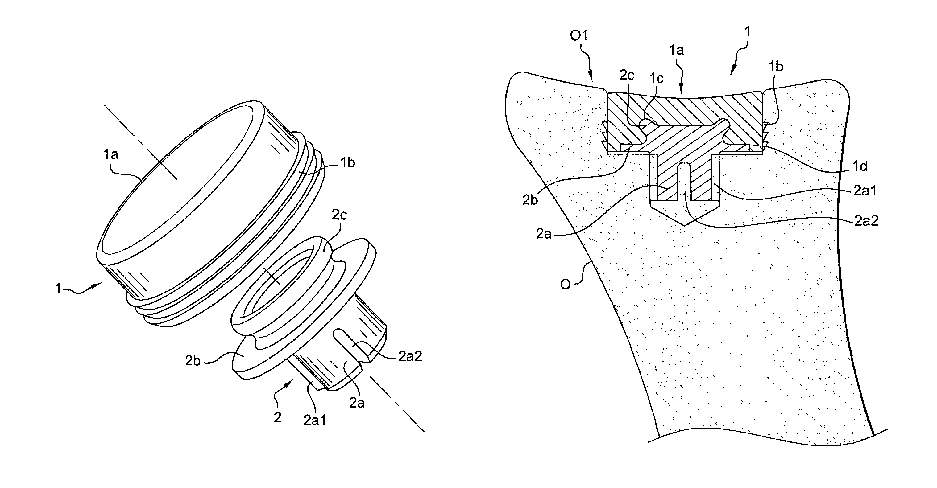
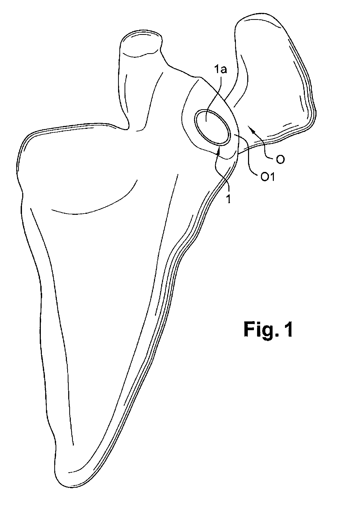
[0018]The scapula, shown in FIG. 1 is labelled as (O), whereas the anatomical glenoid cavity which will receive the implant is labelled as (O1).

[0019]According to a basic characteristic of the invention, the glenoid implant is made to be embedded in the glenoid cavity, with the objective of simply replacing the cartilage, without modifying its biomechanical architecture.

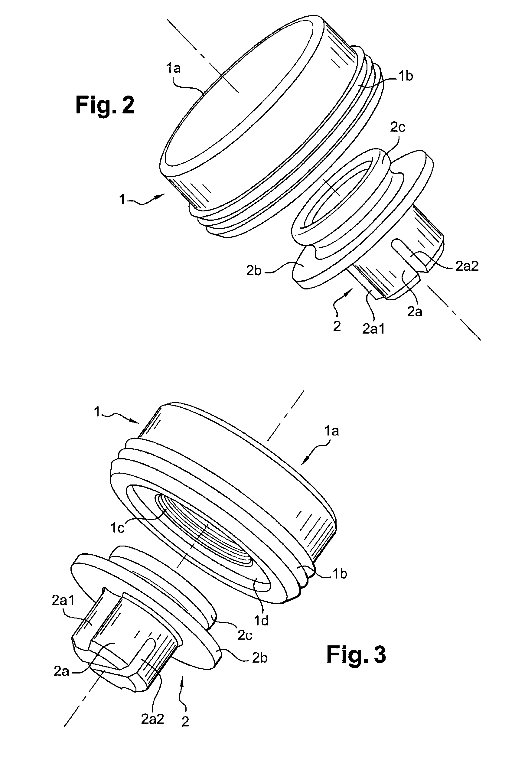
[0020]The implant comprises a polyethylene cup (1) with a concave load-bearing and sliding surface (1a) for the articulation of the prosthetic humeral head (not shown).

[0021]According to the invention, the cup (1) has positioning and fixation devices, e.g., deformable stabilization lamellae (1b), complementary shapes (1c), and / or recess (1d) described below, for it to be embedded in a site of complementary shape made in the spongy bone of the glenoid cavity (O1). After fixation, the load-bearing and sliding surface (1a) of the cup (1), which is generally round in shape, is congruent with the anatomical cavity of the ...


PUM


Abstract

A cup intended to interact with a prosthetic humeral head has a generally circular shape and positioning and anchoring devices for embedding the cup in an anatomical glenoid cavity in such a way that a load-bearing and sliding surface of the cup is integrated into the continuity of the anatomical cavity so as to be perfectly congruent with the humeral head.

Description

CROSS REFERENCE TO RELATED APPLICATIONS[0001]This application is a national stage filing under section 371 of International Application No. PCT / FR2009 / 052711, filed on Dec. 28, 2009, and published in French on Jul. 8, 2010, as WO 2010 / 076534 and claims priority of French application No. 0859102 filed on Dec. 29, 2008, the entire disclosure of these applications being hereby incorporated herein by reference.BACKGROUND ART[0002]The invention comes within the technical field of orthopaedic implants.[0003]More particularly, the invention concerns arthroplasty of the shoulder joint, particularly treatment of centred glenohumeral osteoarthritis.[0004]In a way well known to those working in the field, the surgeon implants a glenoid prosthesis to compensate for the wear in an arthritic glenoid.[0005]Essentially, this type of prosthesis generally consists of either a cemented polyethylene cup or a non-cemented tray to receive a polyethylene cup which will be in contact with a prosthetic hume...

Claims


Application Information

Patent Timeline
IPC IPC(8): A61F2/40
CPCA61F2/4081
Inventor CAPON, DIDIERGONZALVEZ, MARTINHANDELBERG, FRANCKISIDRO, ALBERTLAQUES, DAMIENDE LA SELLE, HUGUESVEDEL, FRANCOISALEPEE, CHRISTOPHE
Owner ASTON MEDICAL DEV
Why Eureka
Try Eureka