Linear vibrator having exposure hole or groove in the cover

a linear vibrator and cover technology, applied in the field of linear vibrators, can solve the problems of shortening the service life of the motor and not having the effect of sufficient vibration for the touch screen, and achieve the effect of smooth flow

Inactive Publication Date: 2014-05-13
MPLUS
View PDF14 Cites 1 Cited by
  • Summary
  • Abstract
  • Description
  • Claims
  • Application Information

AI Technical Summary

Benefits of technology

[0015]An aspect of the present invention is to provide a linear vibrator having compactness and slimness by changing the structure of a coil generating electromagnetic force for vibrations and a magnet, while preventing the performance and characteristics thereof from being degraded by a vibrating component.
[0025]The linear vibrator may further include a yoke plate formed on at least one surface of the magnet and allowing magnetic flux to smoothly flow to the magnet through the coil.

Problems solved by technology

However, a brush-type structure using the commutator may cause mechanical friction and electrical sparks as well as the generation of foreign objects when the brush passes through a clearance between segments of the commutator when the motor is rotated, so that the service life of the motor may be shortened.
In addition, since it takes time to reach an amount of target vibrations due to rotational inertia when voltage is applied to the motor, there may be a problem in which a sufficient amount of vibrations for the touch screen may not be implemented.
However, a linear vibrator according to the related art have a problem in that the performance and characteristics thereof are changed by components that vibrate in an interior space of the linear vibrator, and this may eventually affect the portable electronic device adopting the above-described linear vibrator.

Method used


Image

  • Linear vibrator having exposure hole or groove in the cover
  • Linear vibrator having exposure hole or groove in the cover
  • Linear vibrator having exposure hole or groove in the cover

Examples


Embodiment Construction

[0035]Embodiments of the present invention will now be described in detail with reference to the accompanying drawings. However, it should be noted that the spirit of the present invention is not limited to the embodiments set forth herein and those skilled in the art and understanding the present invention can easily accomplish retrogressive inventions or other embodiments included in the spirit of the present invention by the addition, modification, and removal of components within the same spirit, but those are to be construed as being included in the spirit of the present invention.

[0036]Further, like reference numerals will be used to designate like components having similar functions throughout the drawings within the scope of the present invention.

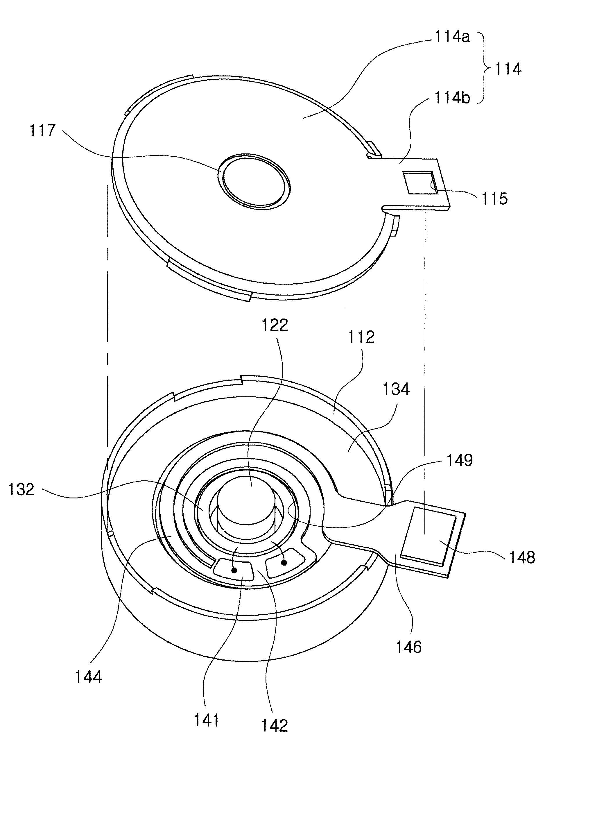
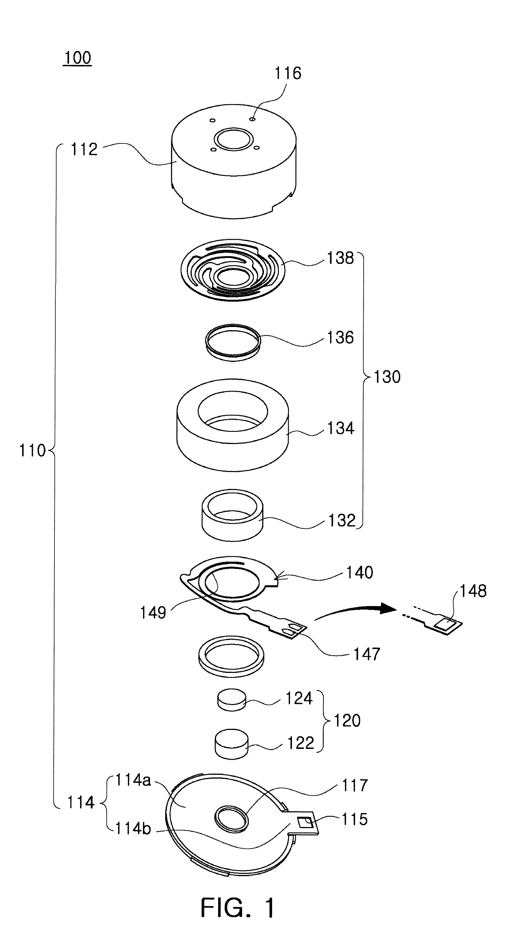
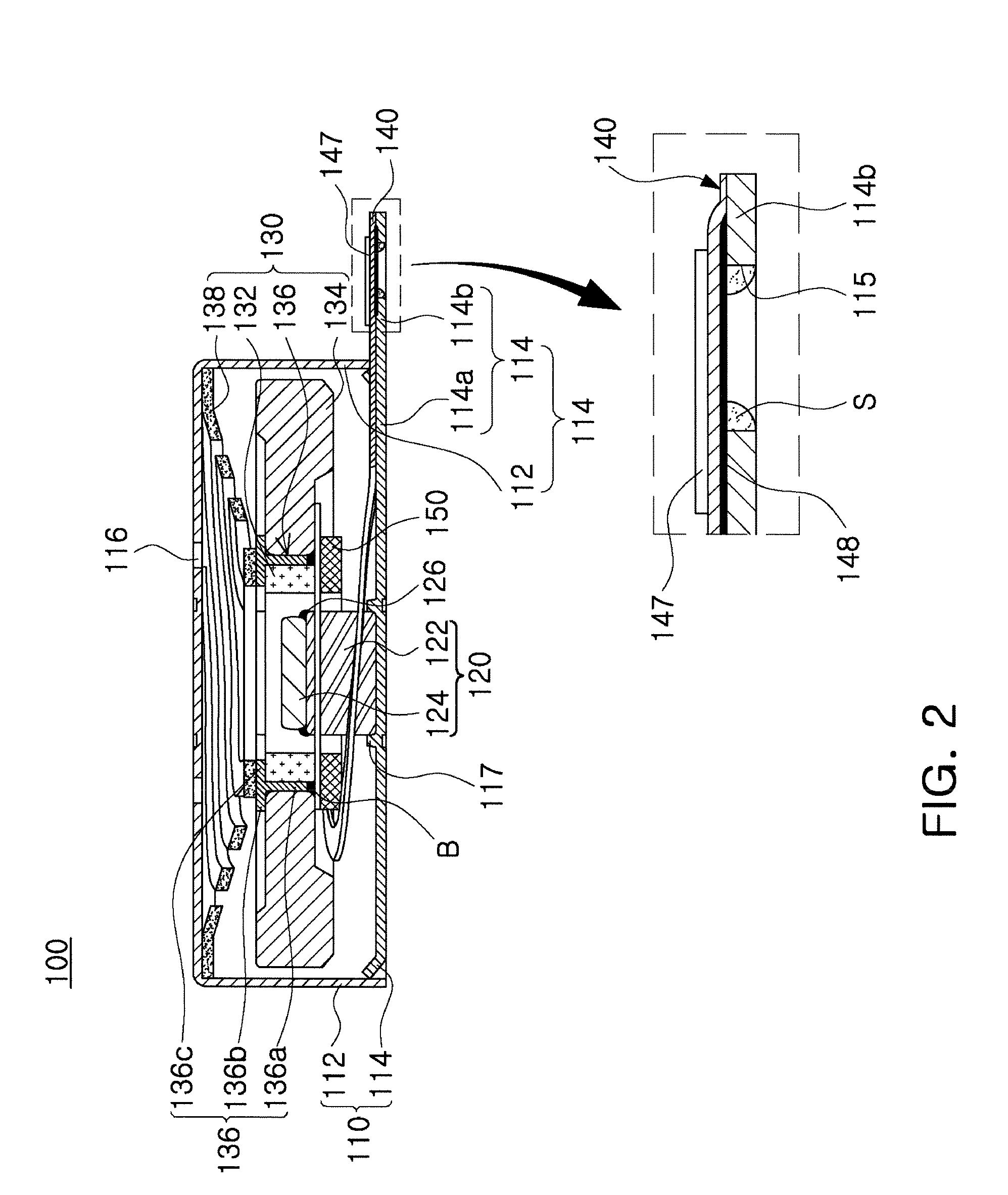
[0037]FIG. 1 is a schematic exploded perspective view illustrating a linear vibrator according to an embodiment of the present invention, FIG. 2 is a schematic cross-sectional view illustrating a linear vibrator according to an embo...


PUM


Abstract

A linear vibrator includes a fixed part providing an interior space having a predetermined size; at least one magnet disposed in the interior space and generating magnetic force; a vibration part including a coil facing the magnet and generating electromagnetic force through interaction with the magnet and a mass body; and a substrate having one end coupled to the vibration part to thereby serve as a free end, and the other end including a copper foil pattern portion coupled to the fixed part to thereby serve as a fixed end. The fixed part includes an exposure hole penetrating a top and bottom surface thereof or an exposure groove recessed from an outer end of the fixed part. The exposure hole or groove is formed on the protrusion portion. The copper foil pattern portion is coupled with a part of the protrusion portion defining the exposure hole or groove.

Description

CROSS-REFERENCE TO RELATED APPLICATIONS[0001]This application claims the priority of Korean Patent Application No. 10-2011-0094435 filed on Sep. 20, 2011, in the Korean Intellectual Property Office, the disclosure of which is incorporated herein by reference.BACKGROUND OF THE INVENTION[0002]1. Field of the Invention[0003]The present invention relates to a linear vibrator, and more particularly, to a linear vibrator capable of generating vibrations when mounted in a portable electronic device.[0004]2. Description of the Related Art[0005]Recently, the release of personal portable terminals having large LCD screens provided for user convenience has significanity increased. Accordingly, a touch screen scheme has been adopted therein, and a vibration motor has been used so as to generate vibrations when a touch is applied to a touch screen.[0006]The vibration motor converts electrical energy into mechanical vibrations using a principle of generating electromagnetic force, and is mounted ...

Claims


Application Information

Patent Timeline
Patent Type & Authority Patents(United States)
IPC IPC(8): H02K41/03H02K35/00H02K33/00
CPCH02K33/18H02K33/02
Inventor JEONG, SEUNG, HYEON
Owner MPLUS
Why Eureka
Try Eureka