Spark plug

a technology of spark plugs and plugs, applied in the field of spark plugs, can solve problems such as misfire associated with discharge abnormalities, and achieve the effect of effectively restrainting the generation of discharge abnormalities and preventing the generation of metal powder through wear

Active Publication Date: 2014-05-13
NGK SPARK PLUG CO LTD
View PDF12 Cites 2 Cited by
  • Summary
  • Abstract
  • Description
  • Claims
  • Application Information

AI Technical Summary

Benefits of technology

[0006]The present invention has been conceived in view of the above circumstances. An object of the present invention is to provide a spark plug whose terminal electrode has a relatively long leg portion and where breakage of the terminal electrode is more reliably prevented.
[0024]In this connection, according to the above configuration 6, the head portion of the terminal electrode has a protrusion. Through insertion of the protrusion into an end portion of the coil spring, movement of the coil spring relative to the head portion can be restrained. As a result, the generation of metal powder through wear can be more reliably prevented, and in turn, the generation of discharge abnormality can be effectively restrained.

Problems solved by technology

However, increasing an applied voltage may cause current to leak between the terminal electrode and the metallic shell in such a manner as to creep (i.e., migrate) onto the surface of the insulator, potentially resulting in the occurrence of misfire associated with discharge abnormality.

Method used


Image

  • Spark plug
  • Spark plug
  • Spark plug

Examples


Embodiment Construction

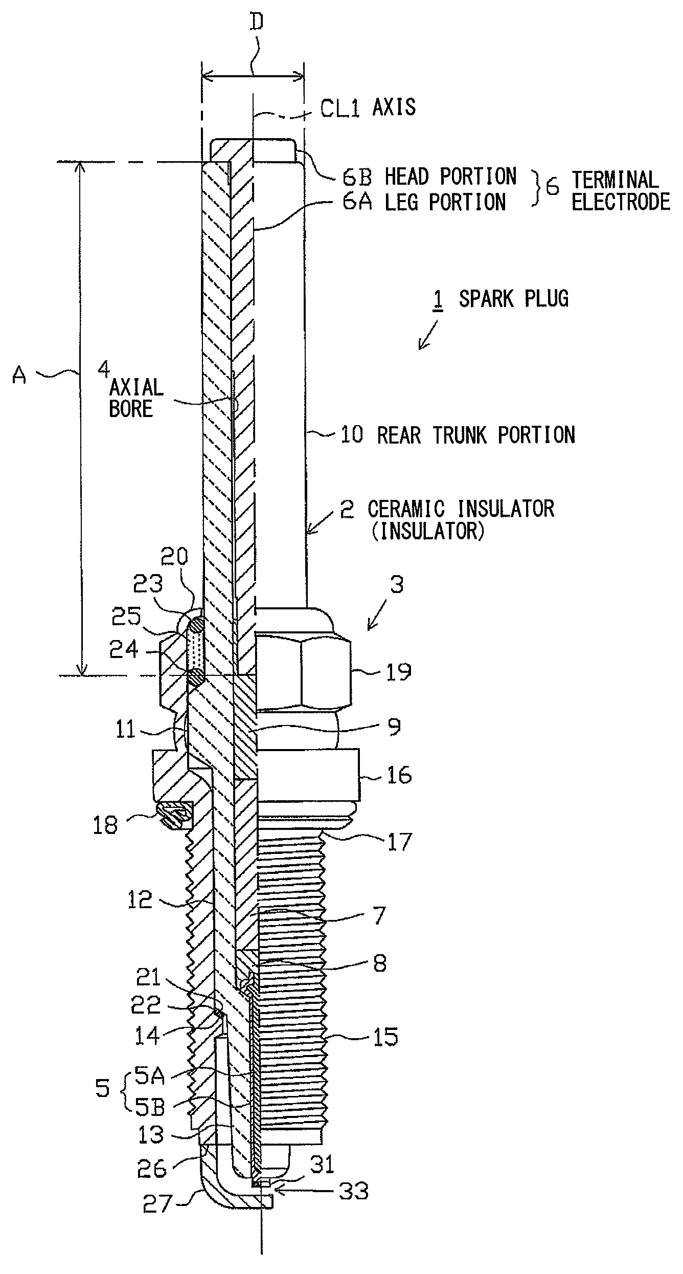
[0032]An embodiment of the present invention will next be described with reference to the drawings. FIG. 1 is a partially cutaway front view showing a spark plug 1. In FIG. 1, the direction of an axis CL1 of the spark plug 1 is referred to as the vertical direction. In the following description, the lower side of the spark plug 1 in FIG. 1 is referred to as the front end side of the spark plug 1, and the upper side as the rear end side.

[0033]The spark plug 1 includes a tubular ceramic insulator 2 and a tubular metallic shell 3, which holds the ceramic insulator 2 therein.

[0034]The ceramic insulator 2 is formed from alumina or the like by firing, as well known in the art. The ceramic insulator 2, as viewed externally, includes a rear trunk portion 10 formed on the rear end side. A large-diameter portion 11 is located frontward of the rear trunk portion 10 and projects radially outward. An intermediate trunk portion 12 is located frontward of the large-diameter portion 11 and is small...


PUM


Abstract

A spark plug includes a ceramic insulator having an axial bore extending in the direction of an axis (CL1) and a terminal electrode inserted into the axial bore. The terminal electrode includes a rodlike leg portion inserted into the a rear end portion of the axial bore and a head portion exposed at the rear end of the ceramic insulator. A front end subportion of the leg portion of the terminal electrode is fixed to the ceramic insulator, and the leg portion has a length of 35 mm or more along the axis (CL1). The center of gravity of the terminal electrode is located in the interior of the ceramic insulator.

Description

FIELD OF THE INVENTION[0001]The present invention relates to a spark plug for use in an internal combustion engine or the like.BACKGROUND OF THE INVENTION[0002]A spark plug is used in an internal combustion engine or the like and typically includes an insulator having an axial bore extending in the axial direction. A center electrode is provided at the front end side of the axial bore, and a terminal electrode is provided at the rear end side of the axial bore. The terminal electrode includes a head portion which is exposed at the rear end of the insulator and to which a plug cap or the like is to be attached for supply of power. The terminal electrode further includes a rodlike leg portion which is inserted into the axial bore of the insulator and whose front end subportion is fixed to the insulator by means of a glass seal or the like. A cylindrical metallic shell is fixed to an outer circumference of the insulator. A ground electrode is joined to a front end portion of the metall...

Claims


Application Information

Patent Timeline
Patent Type & Authority Patents(United States)
IPC IPC(8): H01T13/20
CPCH01T13/04H01T13/38H01T21/02H01T13/20
Inventor KATO, TOMOAKI
Owner NGK SPARK PLUG CO LTD
Why Eureka
Try Eureka