Insert, holder, and cutting tool using said insert and holder

a technology of inserts and holder holders, which is applied in the field of inserts, holder holders and cutting tools, can solve the problems of poor index accuracy and deterioration of rigidity of inserts, and achieve the effect of sufficient rigidity and better adjustment accuracy

Inactive Publication Date: 2014-05-20
KYOCERA CORP
View PDF16 Cites 0 Cited by
  • Summary
  • Abstract
  • Description
  • Claims
  • Application Information

AI Technical Summary

Benefits of technology

[0007]The objective of the present invention is to provide an insert with better accuracy for adjustment while having sufficient rigidity, a holder for the insert, and a cutting tool comprising the insert and the holder.

Problems solved by technology

However, although the position in the axial direction is determined with relatively good accuracy, index accuracy regarding the center height of the insert is poor.
Furthermore, because the plane portion on the upper surface side is provided, the cross-section area of the insert becomes small, resulting in a problem of deterioration in its rigidity.Patent Document 1: Japanese Unexamined Patent Application Publication No. 2001-71204

Method used


Image

  • Insert, holder, and cutting tool using said insert and holder
  • Insert, holder, and cutting tool using said insert and holder
  • Insert, holder, and cutting tool using said insert and holder

Examples


Embodiment Construction

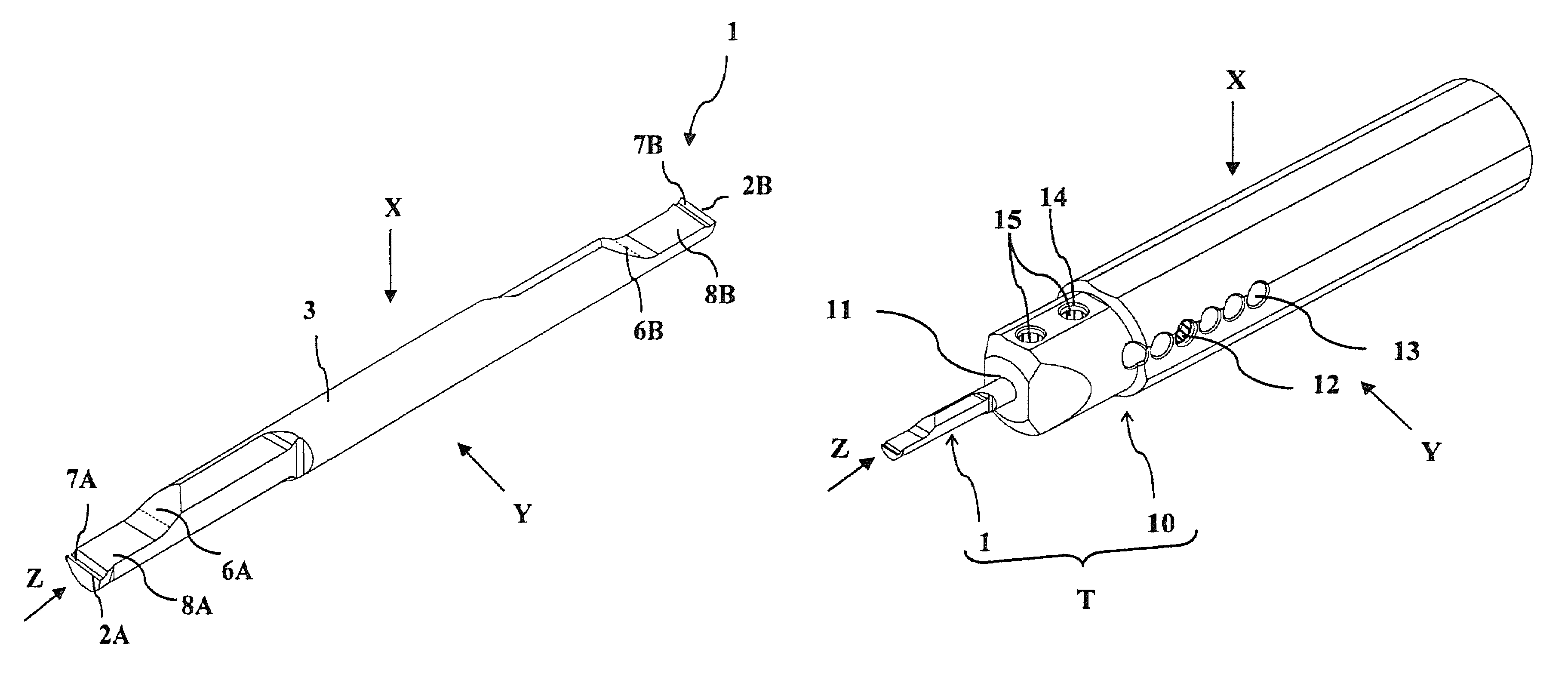
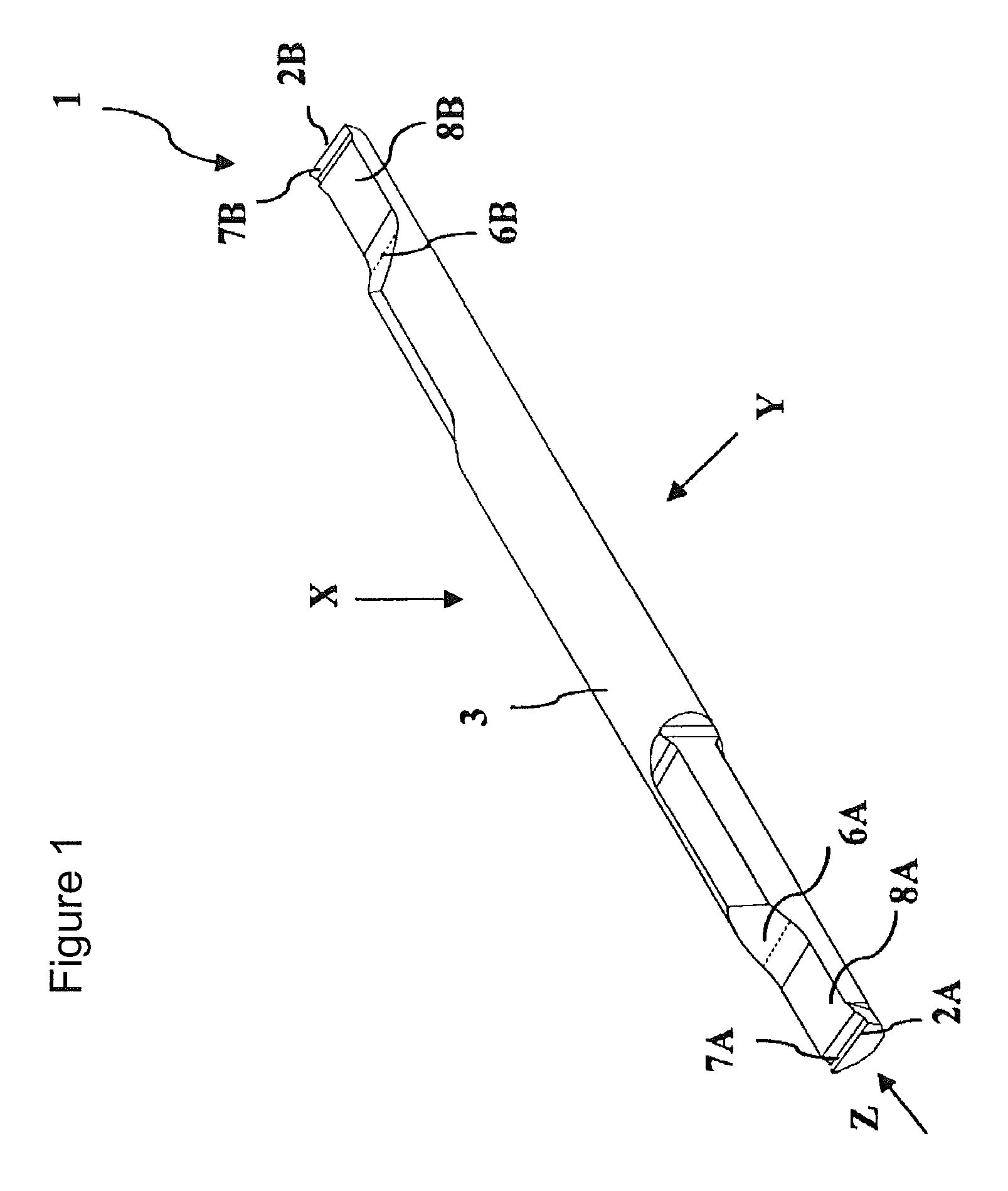
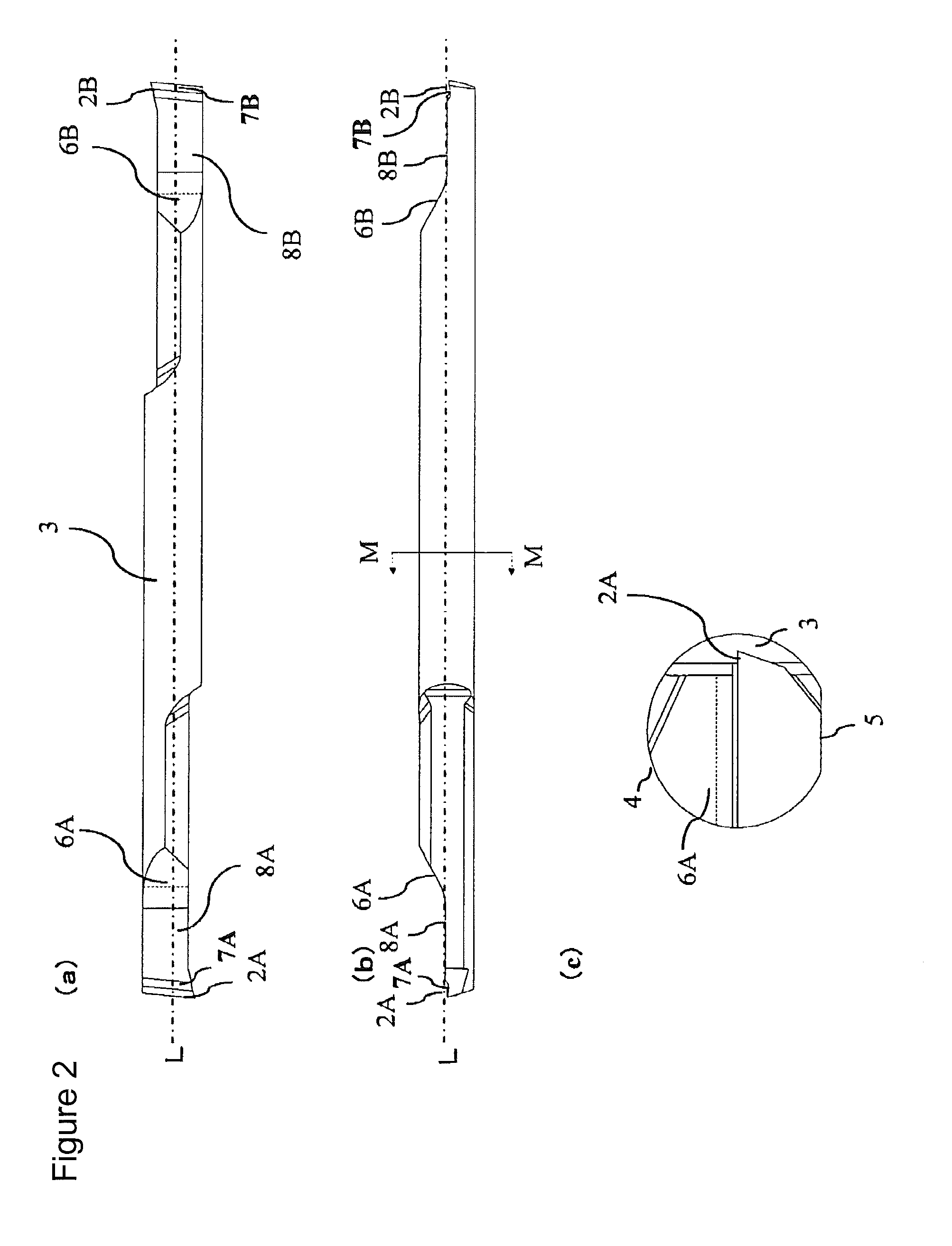
[0009]In an embodiment, a chip pocket is formed between the rising surface and the cutting edge provided on the same side when viewed from the shank part.

[0010]In an embodiment, the rising surface is flat in a cross-sectional view perpendicular to the longitudinal direction and the end part thereof connected to the chip pocket is concave-shaped when viewed from the side surface parallel to the longitudinal direction.

[0011]In an embodiment, in a cross-sectional view perpendicular to the longitudinal direction, a flat part is formed on the outer periphery of the shank part, on a side opposite to the position at which the rising surface is formed.

[0012]A holder of the present invention comprises an insertion hole at the tip end part for inserting and securing the insert, with an adjustment member in abutting contact with the rising surface of the insert provided in the insertion hole thereof.

[0013]In an embodiment, an adjustment member mounting-hole penetrating from the outer periphera...


PUM

PropertyMeasurementUnit
distanceaaaaaaaaaa
diameteraaaaaaaaaa
heightaaaaaaaaaa

Abstract

Provided is an insert that has good positioning precision and sufficient rigidity. Said insert is rod-shaped and has: a shank part; cutting blades formed on both sides of the shank part; and raised surfaces that are positioned between the cutting blades and the shank part and bulge such that parts farther away from the cutting blades are progressively closer to the outer surface of the shank part. In a side view, the rake face of the cutting blade on one side and the raised surface on the other side are disposed in the same direction with respect to the axis of rotation of the shank part.

Description

CROSS-REFERENCE TO RELATED APPLICATION[0001]This application is a national phase of the International Patent Application PCT / JP2010 / 060659 filed on Jun. 23, 2010 that claims the priority from the Japanese patent applications 2009-154341 filed on Jun. 29, 2009 and 2009-177724 filed on Jul. 30, 2009.BACKGROUND OF THE INVENTION[0002]The present invention relates to insert, holder and cutting tool using the same.[0003]Conventionally, those manufactured by inserting, into a holder, a substantially rod-shaped insert (hereinafter simply referred to as an insert) that has a cutting edge on both ends thereof, and is clamped by tightening with a bolt, are known as a cutting tool used for grooving an inner diameter or threading.[0004]Patent Document 1, for example, discloses a cutting tool manufactured by inserting, into a hole of a holder, one end of a substantially rod-shaped insert having a cutting edge on both ends thereof. Also, disclosed is that the position in the axial direction of the...

Claims


Application Information

Patent Timeline
Patent Type & Authority Patents(United States)
IPC IPC(8): B23B29/04B23B31/107
CPCB23B2250/16B23B27/007B23B29/043B23B2270/14B23B27/045Y10T82/2589Y10T407/2222Y10T407/2262Y10T407/228Y10T407/2284Y10T407/24
Inventor KOBAYASHI, YOUJI
Owner KYOCERA CORP
Why Eureka
Try Eureka