
LED light module with light pipe and reflectors

a technology of light pipe and reflector, which is applied in the direction of instruments, lighting and heating apparatus, fibre light guides, etc., can solve the problems of reducing the useful life of current led, requiring less energy to incorporate leds, and exhibiting a relatively short life in use, so as to achieve economic manufacture and design, the effect of long life in us

Inactive Publication Date: 2014-05-20
REBO LIGHTING & ELECTRONICS LLC
View PDF52 Cites 21 Cited by
  • Summary
  • Abstract
  • Description
  • Claims
  • Application Information

AI Technical Summary

Benefits of technology

The patent describes a module that can be used in various applications such as tail lamps, turn indicators, and CHMSLs. It is cost-effective and long-lasting in use.

Problems solved by technology

While incandescent bulbs have exhibited a long and successful reign in vehicle applications, they are known to use a relatively large supply of energy and exhibit a relatively short life in use.
Unfortunately, current modules incorporating LEDs, although requiring less energy and exhibiting a increased useful life, also have drawbacks.
In addition, the current LED light modules suffer from emitted light inefficiencies.
The inefficiencies are due, at least in part, to the inability of known configurations and arrangements of reflectors to reflect a uniform light pattern of the light emitted directly from the LEDs toward the surrounding area desired to be illuminated.
As such, although an individual LED typically exhibits a longer useful life and requires less energy than a single incandescent bulb, the need to incorporate multiple LEDs into a light module negates the benefits of using LEDs in lieu of incandescent bulbs.

Method used


Image

  • LED light module with light pipe and reflectors
  • LED light module with light pipe and reflectors

Examples


Embodiment Construction

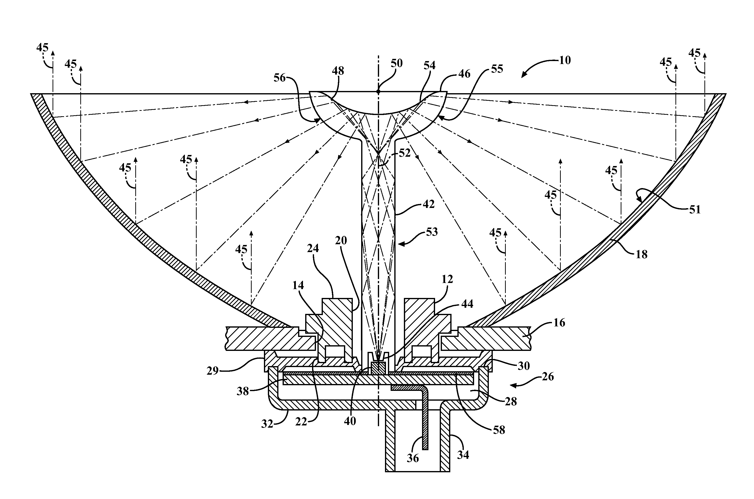
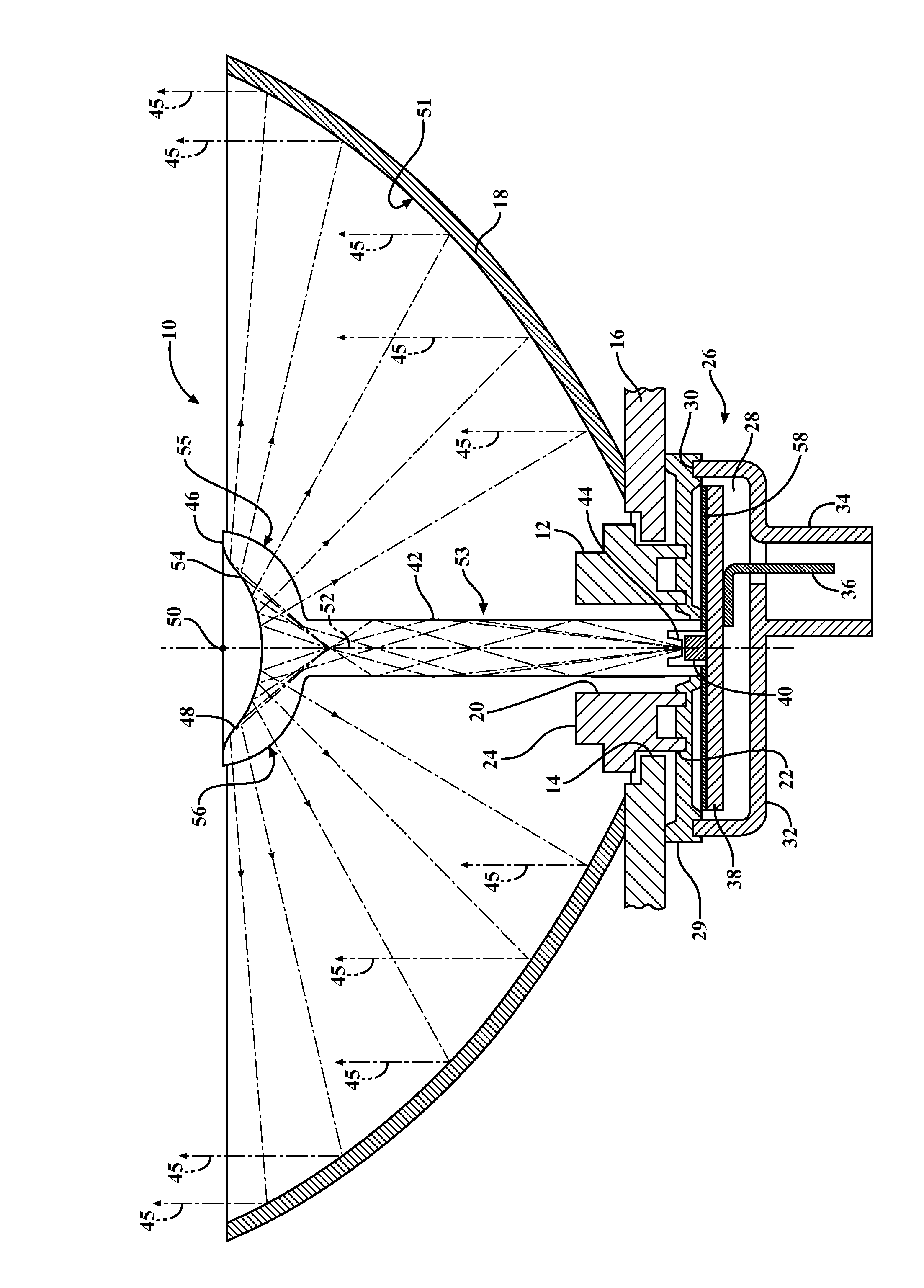
[0017]Referring in more detail to the drawings, FIG. 1 illustrates a LED light pipe module, referred to hereafter as light module or simply module 10, constructed in accordance with one aspect of the invention. The module 10 includes a socket 12 configured for receipt within an opening 14 of a housing 16. The housing 16 has a main hyperbolic reflector 18 fixed thereto. The socket 12 has a through passage 20 extending between a proximal end 22 and a distal end 24. The module 10 further includes a base 26 having an inner cavity 28 bounded by opposite ends 30, 32. One end 30 of the base 26 is operably attached to the proximal end 22 of the socket 12, such as via a seal member 29, and the other end 32 is configured to provide a plug receptacle 34. An electrical connector 36 is disposed at least in part in the plug receptacle 34 and a printed circuit board (PCB) 38 is disposed in the inner cavity 28 in electrical communication with the electrical connector 36.

[0018]Further, a single LED ...


PUM


Abstract

An economical LED light module configured to emit a uniform pattern of light from a single LED utilizing a minimal amount of energy and exhibiting a long and useful life is provided. The LED light module includes a main hyperbolic reflector and a plug receptacle having an electrical connector configured for electrical communication with a power source. A LED is mounted in electrical communication with the electrical connector. An elongate light pipe extends between a light receiving end configured to receive light emitted from the LED and a light emitting end. The light emitting end has a parabolic reflector positioned concentrically about a focal point of the hyperbolic reflector.

Description

CROSS-REFERENCE TO RELATED APPLICATION[0001]This application claims the benefit of U.S. Provisional Application Ser. No. 61 / 384,899, filed Sep. 21, 2010, which is incorporated herein by reference in its entirety.BACKGROUND OF THE INVENTION[0002]1. Technical Field[0003]This invention relates generally to light emitting modules, and more particularly to light emitting modules having a light emitting diode (LED) configured in optical communication with a light pipe.[0004]2. Related Art[0005]It is well known to utilize light modules having incandescent bulbs in vehicle applications. While incandescent bulbs have exhibited a long and successful reign in vehicle applications, they are known to use a relatively large supply of energy and exhibit a relatively short life in use. Efforts to combat these and other problems associated with incandescent bulbs include incorporating LEDs into light modules in lieu of incandescent bulbs. Unfortunately, current modules incorporating LEDs, although r...

Claims


Application Information

Patent Timeline
Patent Type & Authority Patents(United States)
IPC IPC(8): F21V7/09F21V7/06G02B6/36F21V7/07
CPCF21S48/2237F21V7/09F21S48/212F21K9/52F21S48/2293F21V7/07F21S48/215G02B6/36F21Y2101/02F21S48/2206G02B6/0008F21V7/06F21K9/61F21Y2115/10F21S43/195F21S43/14F21S43/27F21S43/237F21S43/251F21V13/04G02B6/00
Inventor SIMCHAK, JEFFREYWONG, JEREMY
Owner REBO LIGHTING & ELECTRONICS LLC
Learn More