Non-contact communication device and method of operating the same

Active Publication Date: 2014-05-20
NXP BV
View PDF7 Cites 3 Cited by
  • Summary
  • Abstract
  • Description
  • Claims
  • Application Information

AI Technical Summary

Benefits of technology

[0010]It is an object of the present invention to provide an alternative non-contact communication device which can be tuned.
[0014]In embodiments the phase detector is a passive phase detector. A passive phase detector does not require the relatively high level of energy typically required by active phase detectors. For active tags this energy may be available, but is unlikely to be available to passive tags, in which the use of a passive phase detector thus may provide a significant advantage.
[0018]In embodiments, the first power output has at least one of more stages and a smaller time constant than the second power output. Using more stages for the first output helps to build quickly sufficient voltage under detuning conditions. A smaller time constant helps to speedup the tuning process. Faster response is thereby facilitated, which is beneficial, since a tag should be able to respond to the reader command within a given amount of time.

Problems solved by technology

Use of a phase detector results in a device which is less sensitive to amplitude modulated noise than known devices, since noise tends to have a more significant impact on the amplitude than the phase of the input RF signal.

Method used


Image

  • Non-contact communication device and method of operating the same
  • Non-contact communication device and method of operating the same
  • Non-contact communication device and method of operating the same

Examples


Embodiment Construction

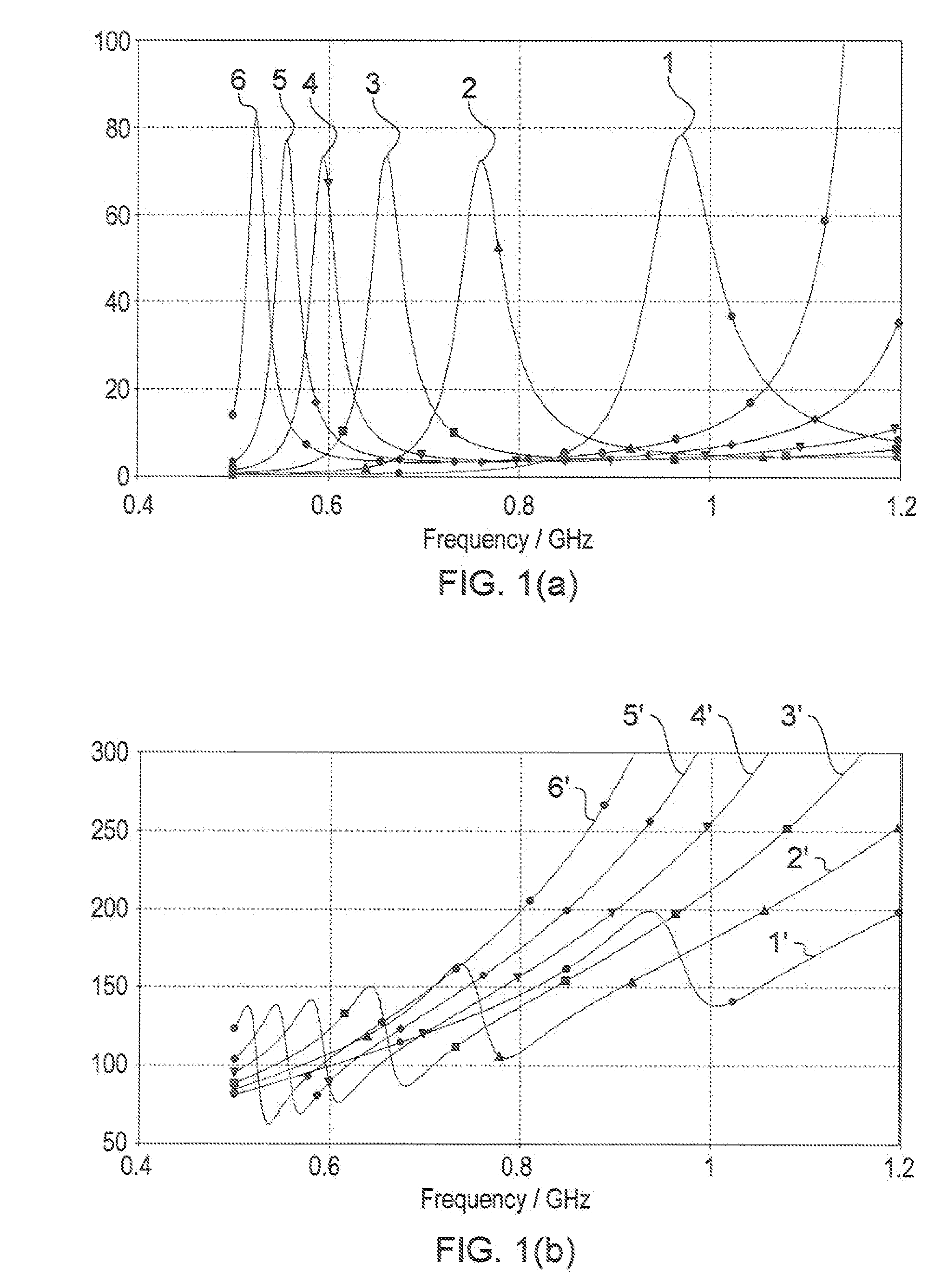
[0037]FIG. 1(a) is a graph showing the real part of an antenna's impedance, under simulations in which the relative permittivity εr of the surrounding material is varied between 1 and 10. Plotted on a relative scale against frequency, is the imaginary part 1 of the antenna impedance, tuned to a frequency of around about 960 MHz, surrounded by air or another medium having a relative permittivity εr equal to unity. Also shown on the graph are plots 2-6 of the impedances of the same antenna, when surrounded by a medium having relative permittivity value εr of 2.8, 4.6, 6.4, 8.2, and 10 respectively. From the graph it is clear that although the magnitude of the peak in the impedance does not vary significantly, the frequency at which the peak occurs, that is to say the tuned frequency of the antenna, reduces from the value around 960 MHz, in the case 1 where the relative permittivity εr is unity, to about 500 MHz for plot 6 in which the relative permittivity εr is 10. Thus a change in r...


PUM


Abstract

A non-contact communication device is disclosed comprising: an antenna having an input impedance and being for receiving an AC signal having a voltage and a current, a main unit comprising a power-extraction unit and a communication unit and having a main unit impedance, a tuning circuit, and a matching network for matching the input impedance to the main unit impedance, characterized in that the tuning circuit comprises a phase detector for detecting a phase difference between the voltage and the current and is configured to adjust the impedance of the matching network in dependence on the phase difference. Also disclosed is a method for tuning a non-contact communication device.

Description

CROSS-REFERENCE TO RELATED APPLICATIONS[0001]This application claims the priority under 35 U.S.C. §119 of European patent application no. 10159383.8, filed on Apr. 8, 2010, the contents of which are incorporated by reference herein.FIELD OF THE INVENTION[0002]This invention relates to non-contact communication devices, and to methods of operating non-contact communication devices.BACKGROUND OF THE INVENTION[0003]Non-contact communication devices are widely used in a range of applications, such as stock control and inventory management, item tracking, security, and the like. Since a basic function of non-contact communication devices is identification of the device or tag, and radio frequencies are used, this technology is also known as RFID (radio frequency identification devices), although should be noted that applications now considerably extend beyond mere simple identification function. Hereinbelow, non-contact communication and RFID shall be used synonymously.[0004]RFID general...

Claims


Application Information

Patent Timeline
Patent Type & Authority Patents(United States)
IPC IPC(8): H04Q9/00
CPCG06K19/07749G06K19/0726
Inventor EL WAFFAOUI, RACHIDMANZI, GIULIANO
Owner NXP BV
Why Eureka
Try Eureka