Light-emitting element driving device and display device

a technology of light-emitting elements and driving devices, which is applied in the direction of lighting apparatus, light sources, instruments, etc., can solve the problems of reducing electric power efficiency, and increasing the power consumption of the constant-current circuit, so as to reduce the maximum voltage, reduce the heat generated, and reduce the power loss

Active Publication Date: 2011-11-24
SATURN LICENSING LLC
View PDF2 Cites 12 Cited by
  • Summary
  • Abstract
  • Description
  • Claims
  • Application Information

AI Technical Summary

Benefits of technology

[0052]According to the present invention, it is possible to reduce the maximum voltage applied to the constant-current circuits, to reduce the power losses caused by the constant-current circuits, and hence to reduce the heat generated thereby.

Problems solved by technology

However, if the forward voltage Vf of each LED varies to a value lower than a standard value, for example, then the voltages applied to the constant-current circuits 5-1, 5-2 increase, increasing power consumption of the constant-current circuits 5-1, 5-2 and reducing electric power efficiency thereof.
Particularly, an increase in the power consumption of the constant-current circuit 5-1 or 5-2 connected to the light emitter 3-1 or 3-2 which is not under the maximum voltage VF is greatly responsible for a reduction in the electric power efficiency, and is also liable to cause the constant-current circuit 5-1 or 5-2 to generate undue heat.

Method used


Image

  • Light-emitting element driving device and display device
  • Light-emitting element driving device and display device
  • Light-emitting element driving device and display device

Examples


first embodiment (

1. First embodiment (first configuration example of light-emitting element (LED) driving device)

second embodiment (

2. Second embodiment (second configuration example of light-emitting element (LED) driving device)

third embodiment (

3. Third embodiment (display device)<

1. First Embodiment

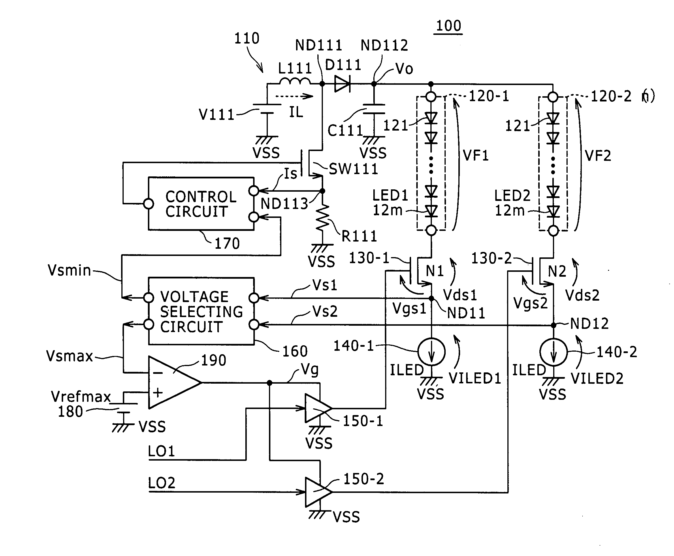
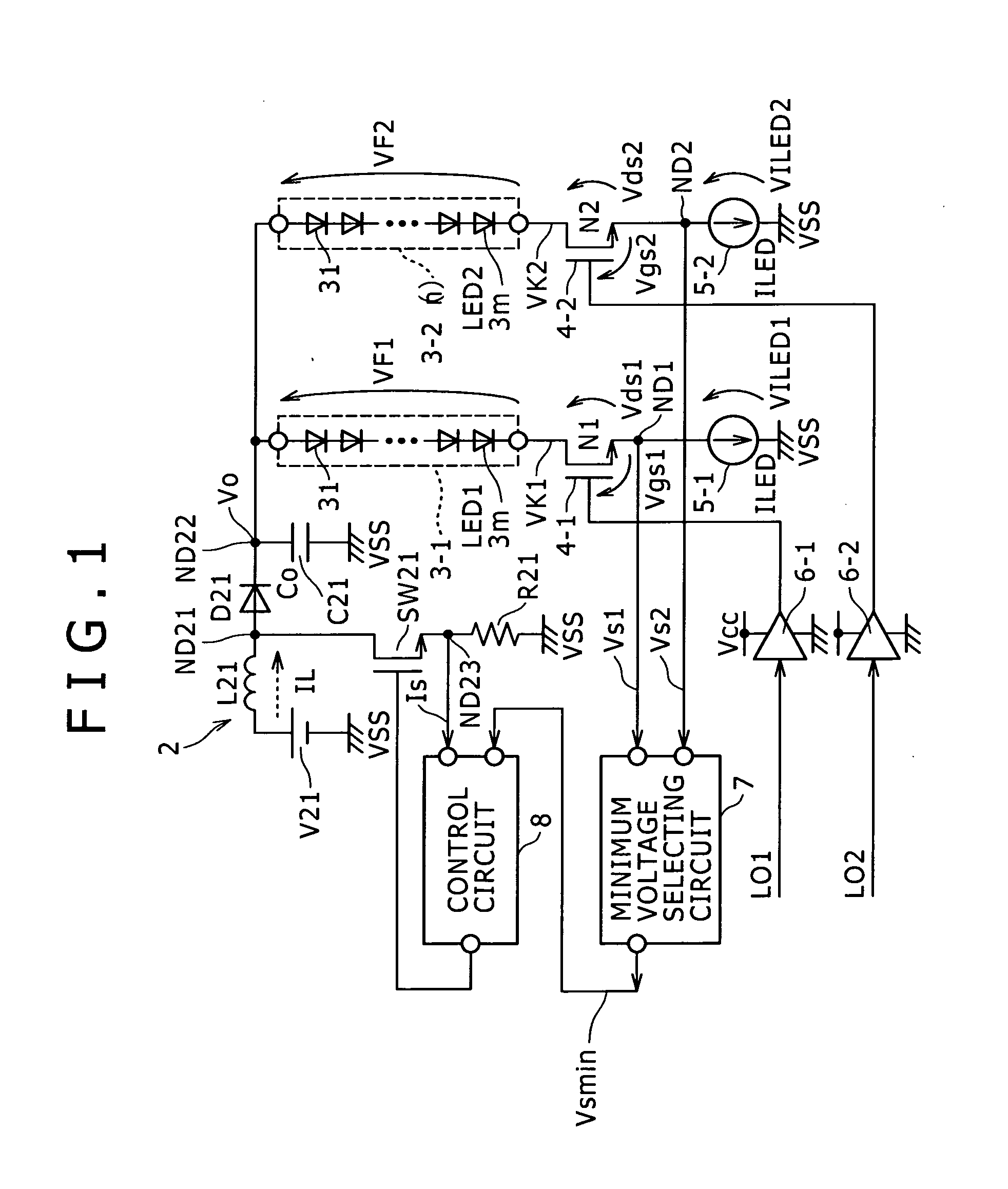
[0061]FIG. 2 is a circuit diagram, partly in block form, of a light-emitting element (LED) driving device according to a first embodiment of the present invention, and FIG. 3 is a circuit diagram, partly in block form, of the light-emitting element (LED) driving device according to the first embodiment of the present invention.

[0062]According to the first embodiment, the LED driving device drives LEDs as light-emitting elements which are electrooptic elements for emitting light whose luminance varies depending on a current flowing therethrough.

[0063]As shown in FIGS. 2 and 3, the LED driving device, generally denoted by 100, includes a booster-chopper-type switching power supply 110 and a plurality of light emitters 120-1 through 120-n (n=2 in FIGS. 2 and 3) as loads including LED arrays each including a plurality of series-connected LEDs. It is assumed that n=2 in the description which follows.

[0064]The LED driving device 100 ...


PUM


Abstract

A light-emitting element driving device includes: a plurality of light emitters; a power supply; a plurality of current control transistors; a plurality of constant-current circuits; a voltage selecting circuit; a control circuit; and a voltage controller.

Description

BACKGROUND OF THE INVENTION[0001]1. Field of the Invention[0002]The present invention relates to a light-emitting element driving device for driving a light-emitting element such as a light-emitting diode (LED) or the like which emits light at a luminance level depending on a current flowing therethrough, and a display device having a non-emission transmissive display unit which incorporates such a light-emitting element driving device.[0003]2. Description of the Related Art[0004]The backlight of a liquid crystal display panel employs LEDs as its light source which have replaced a CCFL (Cold Cathode Fluorescent Lamp) employing a fluorescent tube.[0005]Particularly, backlights including individual primary LEDs such as red LEDs, green LEDs, and blue LEDs for producing white light according to an optical additive color synthesis have been used in television applications as they can easily achieve good color balances. In recent years, white LEDs with improved color rendition have widely...

Claims


Application Information

Patent Timeline
Patent Type & Authority Applications(United States)
IPC IPC(8): H05B37/02
CPCG09G2330/025G09G3/3406
Inventor NAITO, TAKAHIROKATAYAMA, YASUSHINISHINO, TATSUKI
Owner SATURN LICENSING LLC
Why Eureka
Try Eureka