soft switching dc‑dc converter

A technology of DC-DC and converters, applied in the field of soft-switching DC-DC converters, can solve problems such as safety, reliability reduction, high rated voltage, and system cost increase, so as to improve safety and reliability, reduce The effect of reducing the maximum voltage and reducing the switching loss

Active Publication Date: 2017-02-01
HEFEI UNIV OF TECH
View PDF8 Cites 0 Cited by
  • Summary
  • Abstract
  • Description
  • Claims
  • Application Information

AI Technical Summary

Problems solved by technology

This increases the difficulty in the selection of switching tubes and diodes, resulting in higher system costs and lower system security and reliability.
[0003] It can be seen from the above that at present, in the converter, there is still a problem that the switch tube cannot achieve complete zero-voltage turn-on and zero-voltage turn-off; the rated voltage of the switch tube and diode is too high, which increases the difficulty of selecting the switch tube and diode for the converter. The difficulty of the system increases the cost of the system and affects the security and reliability of the system

Method used


Image

  • soft switching dc‑dc converter
  • soft switching dc‑dc converter
  • soft switching dc‑dc converter

Examples


Embodiment 1

[0041] The topological diagram of embodiment 1 is as figure 1 mentioned. In this embodiment, the switch assembly is an anti-blocking switch tube, and a first switch tube S 1 and a diode in series, see the specific structure image 3 301 in.

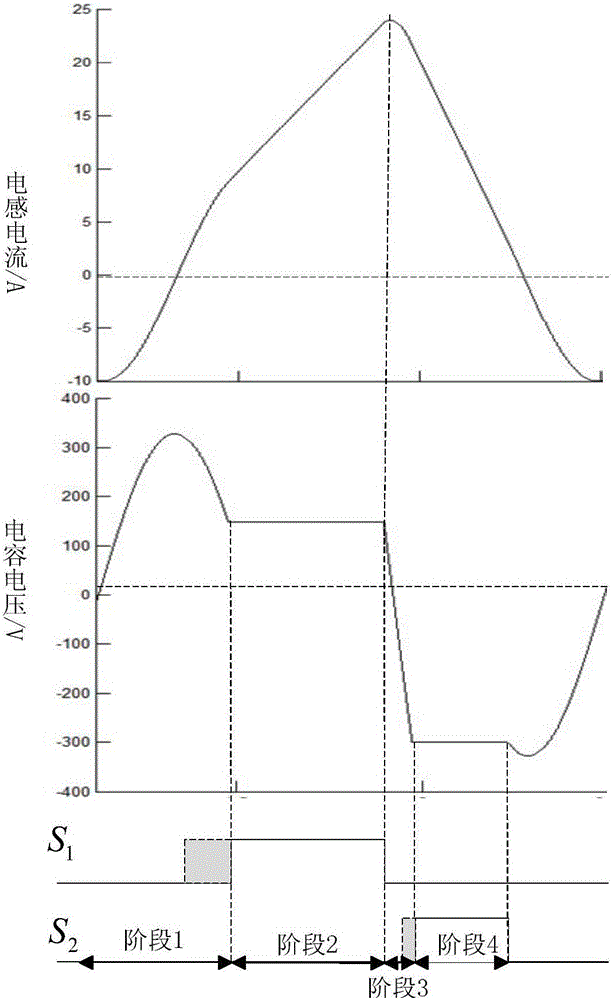
[0042] The working process is mainly divided into four stages. The commutation process is as follows: Figure 4 shown.

[0043] In order to explain the working process of the converter more clearly, let the input voltage be U in , the output voltage is U o , when the voltage on the upper side of the capacitor voltage is greater than the voltage on the lower side, it is a positive voltage, and the downward flow of the inductor current is a positive direction.

[0044] Working stage one: the first switching tube S in this process 1 , the second switch tube S 2 All are in the off state, after the end of the last working stage, the resonant inductance L 2 and resonant capacitor C 2 start to resonate as Figure 4 As shown in (a), w...

Embodiment 2

[0052] The topological diagram of embodiment 2 is as figure 2 mentioned. In this embodiment, the switch assembly is an anti-parallel switch tube, consisting of a first switch tube S 1 and a diode, the diode and the first switch S 1 It is connected in anti-parallel mode, see the specific structure image 3 302 in.

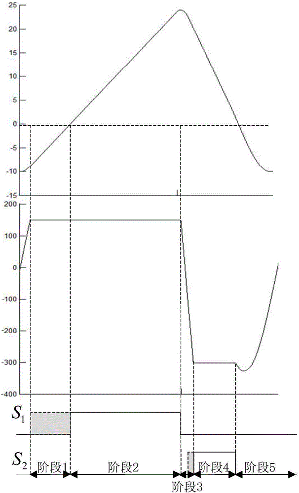
[0053] The working process of the soft-switching DC-DC converter in this embodiment is mainly divided into five stages. The commutation process is as follows: Figure 8 shown.

[0054] In order to explain the working process of the converter more clearly, we set the input voltage as U in , the output voltage is U o , when the voltage on the upper side of the capacitor voltage is greater than the voltage on the lower side, it is a positive voltage, and the downward flow of the inductor current is a positive direction.

[0055] Working stage one: the first switching tube S in this process 1 , the second switch tube S 2 All are in the off state, after the end...


PUM


Abstract

The invention discloses a soft-switching DC-DC converter. The converter comprises an input power supply (Uin), a load (load), a first filter component (101), a first switch tube component (102), a parallel resonant tank (103), a diode component (104), and a second switch tube component (105) and a second filter assembly (106), the switch assembly (S1) in the first switch tube assembly (102) adopts two forms of anti-blocking and anti-parallel, so that the switches in it can realize zero-voltage conduction Turn-on and zero-voltage turn-off effectively improve the efficiency of the converter. By adding the diode component (104), the voltage borne by both ends of the switch tube in the switch component (S1) and the peak value of the reverse voltage borne by the diode are effectively reduced, thereby reducing the requirements of the converter on the switch tube. Thus, the cost of the converter is effectively reduced, and the efficiency, safety and reliability of the system are improved.

Description

technical field [0001] The invention relates to a DC-DC converter, in particular to a soft-switching DC-DC converter. Background technique [0002] The topology diagram of the existing DC-DC converter is as follows Figure 12 As shown, the power switching tube devices all work in the hard switching state, and the on-off state is accompanied by drastic changes in voltage and current, which leads to the problems of high switching loss and serious noise in the existing DC-DC converter. In order to reduce the loss and noise of the power switch tube, the invention patent of Document 1 "A Soft-switching Step-Down DC-DC Converter" (Notice No. CN 101662209 B) proposes a soft-switching step-down DC-DC converter , but its main switching tube can only realize zero-current and zero-voltage turn-off, but cannot realize zero-voltage and zero-current conduction, which limits the effect of reducing the loss of the converter. Document 2 Invention Patent Application "Zero-Current Soft-Switch...

Claims


Application Information

Patent Timeline
Patent Type & Authority Patents(China)
IPC IPC(8): H02M3/335
CPCH02M3/155H02M1/0058Y02B70/10
Inventor 王付胜田龙祥张兴文鹏王东毅欧阳秋杨淑英谢震
Owner HEFEI UNIV OF TECH
Why Eureka
Try Eureka