Integrated portable checkpoint system

a portable checkpoint and checkpoint technology, applied in the direction of material analysis, material analysis using wave/particle radiation, instruments, etc., can solve the problems of affecting the overall society, unable to accommodate additional inspection facilities and difficult to find suitable space along the normal process rou

Inactive Publication Date: 2014-05-20
RAPISCAN SYST INC (US)
View PDF39 Cites 37 Cited by
  • Summary
  • Abstract
  • Description
  • Claims
  • Application Information

AI Technical Summary

Problems solved by technology

Today, billions of dollars are spent on securing borders and checkpoints in certain regions, at an increasing rate, due to a failure to effectively integrate fielded tools and technologies or to design tools in a manner that withstands the rigors and harsh environmental conditions found in certain regions, such as deserts.
These spending increases, while difficult to quantify due to available data on the pace of operations and other factors that might affect costs, tend to have a detrimental effect on society as a whole.
Further, with limited space and a need to expand, finding suitable space to accommodate additional inspection facilities along the normal process route remains difficult.
Additionally, selected locations are not necessarily permanent enough for port operators to commit to the long term installation of inspection equipment.
In either case, the building footprint is significant depending upon the size of cargo containers to be inspected.
This limits the flexibility of dismantling the entire system for optimum portability and adjustable deployment to accommodate a wide array of different sized cargo, shipments, vehicles, and other containers.
As a result these systems can be complicated to deploy and pose several disadvantages and constraints.
For example, in a moving-scan-engine system the movement of the source and detector, relative to a stationary object, may cause lateral twist and lift and fall of the detector or source, due to movement of the scanner over uneven ground, inducing distortions in the scanned images and faster wear and tear of the scanner system.
Such systems that require a detector-mounted boom to unfold during deployment may cause an unstable shift of the center of gravity of the system off the base, causing the system to tip over.
Further, in the case of moving-scan-engine systems using a “swing arm” boom approach, the driver driving the scanner truck is unable to gauge the possibility of hitting the detector box, mounted on a boom, with a vehicle under inspection (VUI), as the detector box is on the other side of the VUI during scanning and not visible to the driver.
Additionally, with moving-scan-engine systems, the truck supporting the scanner system is always required to move the full weight of the scanner regardless of the size and load of the VUI, putting greater strain on the scanning system.
Also disadvantageous in conventional systems is that they suffer from a lack of rigidity, are difficult to implement, and / or have smaller fields of vision.
Further, in the mobile cargo inspection systems known in the art, the boom structures are typically heavy, thereby causing the overall weight of the scanning system to be close to, or even over the allowable axle load limits.
Further, the booms are bulky when stowed such that the vehicle is approximately 4 m high above road level.
This makes a mobile scanning system not only difficult to manoeuvre but also restricts its movement in different territories due to the applicable road restrictions on carriage weight.

Method used


Image

  • Integrated portable checkpoint system
  • Integrated portable checkpoint system
  • Integrated portable checkpoint system

Examples


first embodiment

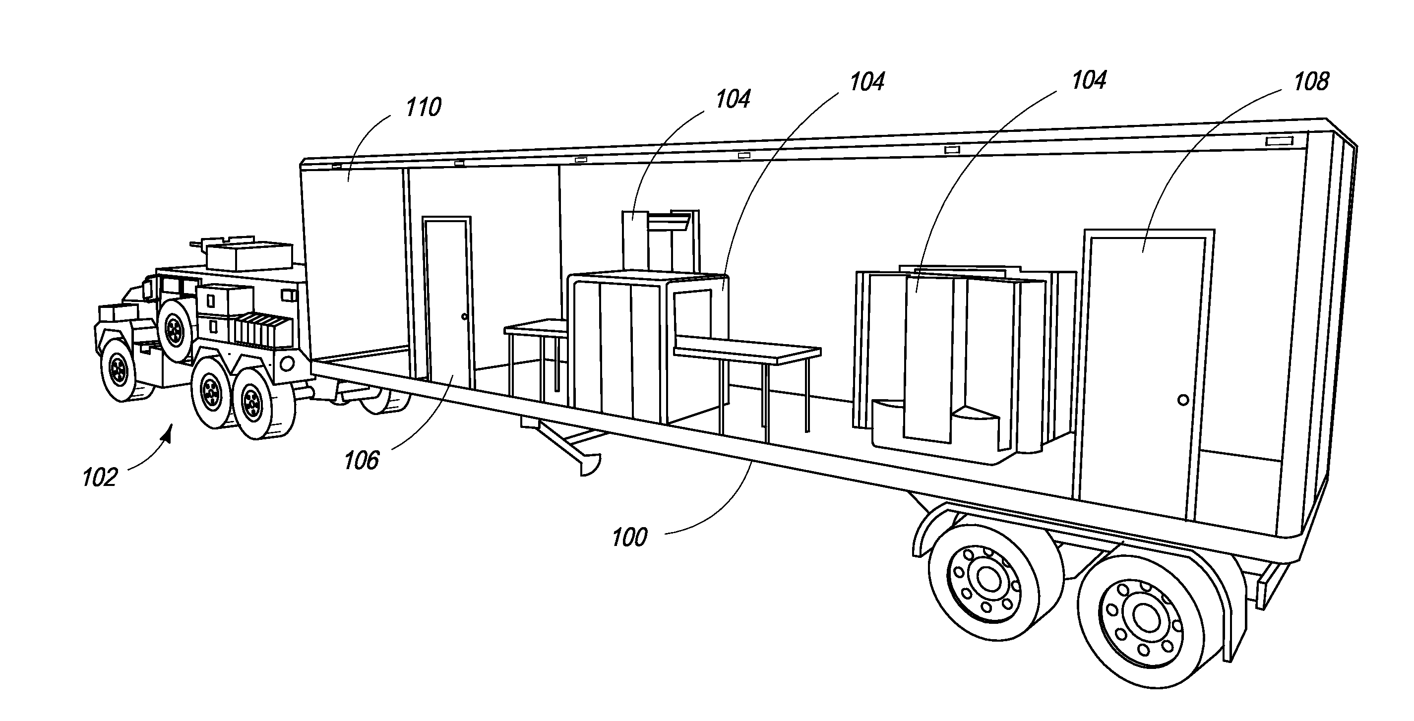
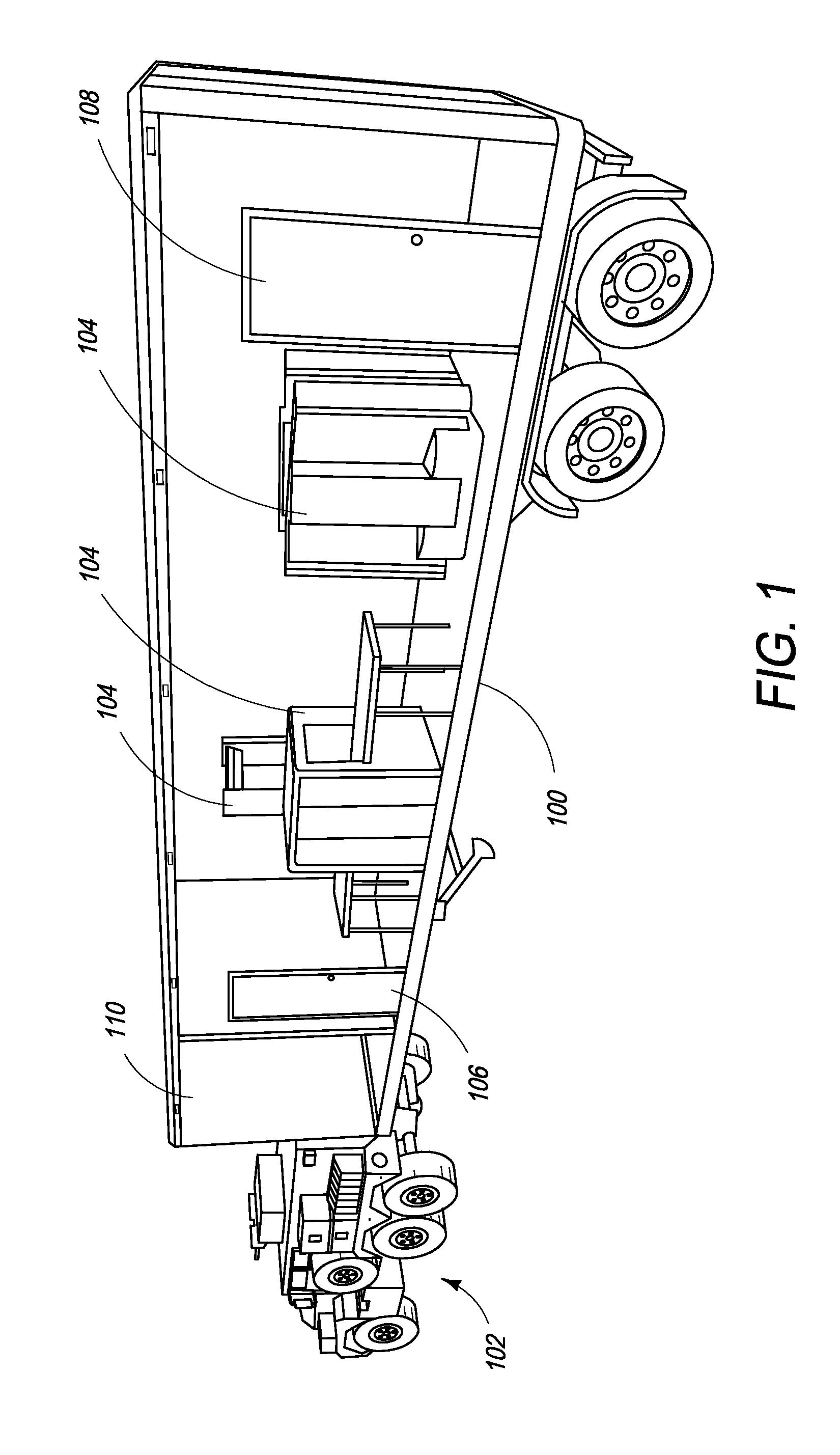
[0059]FIG. 1 is an illustration of the integrated portable checkpoint system of the present invention comprising a single container and a tractor used to mobilize the integrated portable checkpoint container. In one embodiment, the integrated portable checkpoint container 100 is towed to a destination site by MRAP vehicle 102. In one embodiment, checkpoint container 100 comprises at least one internal checkpoint module 104. In order to allow for ingress and egress into and out of the internal checkpoint, in one embodiment the container includes an entrance door 106 on one end of one side of the container and an exit door 108 on the opposite end of the same side of the container to facilitate the flow of traffic.

[0060]In one embodiment, the at least one internal checkpoint module 104 is a baggage scanner similar to ones used at airports to scan carry-on luggage. A conveyor system passes baggage through a housing in which the baggage is subjected to x-rays in order to create an image ...

second embodiment

[0097]In a second embodiment, the boom of the present invention operates in a turntable fashion and comprises a horizontal boom section and a vertical boom section.

[0098]FIG. 7a is a rear view block diagram of one embodiment of a turntable design of the boom 700a of the present invention when fully deployed. In one embodiment, the boom comprises two sections: a horizontal boom section 705a, and a vertical boom section 710a. In this embodiment, an X-ray source 715a is attached to the side of the container 701a. The X-ray source 715a is positioned somewhere between the rear axle and the front of the container 701a. The boom 700a and X-ray source 715a are fixed to a horizontal rail or gantry system 720a that allows for horizontal sliding of both components along the length of the container 701a, between the rear axle and the front of the container 701a. Movement along the rail or gantry system 720a is synced and controlled by a computer so that the two components remain calibrated duri...

third embodiment

[0102]In a third embodiment, the boom of the present invention operates in a turntable fashion and comprises a horizontal boom section and a vertical boom section, and is vertically extendable by use of a hydraulic lift.

[0103]In the turntable with lift embodiment, a hydraulic cylinder or other similar lifting mechanism is included at the pivot point to enable scanning of vehicles with a height greater than that of the inspection container. FIG. 8 is a rear view block diagram of one embodiment of a turntable with vertical lift design of the boom 800 of the present invention in a vertically extended deployed configuration. The boom comprises three sections: a vertical hydraulic cylinder 835, a horizontal boom section 805, and a vertical boom section 810. In this embodiment, an X-ray source 815 is attached to the side of the container 801. The X-ray source 815 is positioned somewhere between the rear axle and the front of the container 801. In one embodiment, the X-ray source is vertic...


PUM

PropertyMeasurementUnit
temperaturesaaaaaaaaaa
heightaaaaaaaaaa
sizeaaaaaaaaaa

Abstract

The present specification discloses a portable system for inspecting objects. The system includes a housing adapted to be carried by a vehicle, which houses a metal detector and an X-ray scanner and further includes a deployable boom positioned on a top surface of the housing. Operationally, the system is transported to a location, persons or objects are inspected by the metal detector or X-ray scanner and the boom is deployed to inspect external cargo. The integrated portable checkpoint system provides security screening and inspection equipment with increased operational capabilities in one fully integrated package.

Description

CROSS-REFERENCE TO RELATED APPLICATIONS[0001]The present specification relies on U.S. Provisional Patent No. 61 / 308,376, entitled “Integrated Checkpoint Container” and filed on Feb. 26, 2010, for priority and is herein incorporated by reference in its entirety.FIELD OF THE INVENTION[0002]The present specification relates to apparatuses for, and methods of, securing a location. More specifically, the present specification discloses methods, apparatuses, and integrated systems for screening individuals and their baggage, shoes, and vehicles with improved throughput, efficiency, and quality. The present specification also relates to an integrated, modular, ruggedized checkpoint system, comprising one or more checkpoint containers, in which all screening capabilities are controlled via a single graphical user interface (GUI) and can be deployed in a military context.BACKGROUND OF THE INVENTION[0003]Protection of deployed military forces is essential to effectively securing the nation. T...

Claims


Application Information

Patent Timeline
Patent Type & Authority Patents(United States)
IPC IPC(8): G01N23/04
CPCG01V5/005G01V11/00G01V5/0033G01V3/165G01V5/0016G01V3/08G01V5/0008
Inventor ARROYO, JR., LUIS E.KOTOWSKI, ANDREAS F.KUMAR, SIVAKANT, PETER
Owner RAPISCAN SYST INC (US)
Why Eureka
Try Eureka