
Repeater for MIMO signals in a network

a technology of mimo signals and repeaters, applied in repeaters/relay circuits, transmission monitoring, baseband system details, etc., can solve the problems of losing all mimo benefits, and achieve the effect of restoring the orthogonal polarization of two signals and lowering the condition number of two signals

Active Publication Date: 2014-05-20
CELLULAR SPECIALTIES
View PDF17 Cites 2 Cited by
  • Summary
  • Abstract
  • Description
  • Claims
  • Application Information

AI Technical Summary

Benefits of technology

This approach enables the maintenance of MIMO benefits by reducing the condition number and improving signal noise ratios, resulting in enhanced throughput and orthogonality, with field tests showing a 70% improvement in MIMO capacity over SISO repeaters.

Problems solved by technology

Consequently, all MIMO benefits are lost.

Method used


Image

  • Repeater for MIMO signals in a network
  • Repeater for MIMO signals in a network
  • Repeater for MIMO signals in a network

Examples


Embodiment Construction

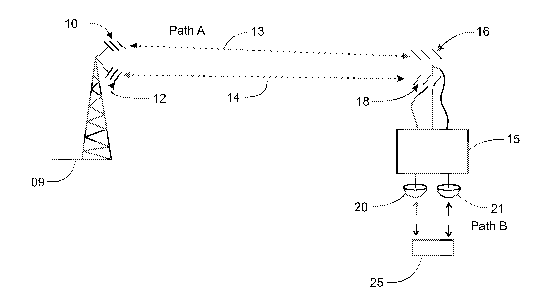
[0014]The present invention is an apparatus and method to repeat MIMO signals in any network. A preferred embodiment comprises a base station 09 in an LTE network for transmitting MIMO signals through orthogonally polarized antennas 10, 12. For example, as is shown on FIG. 4, the orthogonally polarized antennas 10, 12 at base station 8 can be oriented at slant +45° and slant −45° although other orientations for the orthogonally polarized antennas 10, 12, for example, 0° and 90°, may be used. The MIMO signals 13, 14 are orthogonally polarized. Orthogonality is maintained at the dual repeater 14 by using two orthogonally polarized donor antennas 16, 18 with the same orientation, slant +45° and slant −45°. The dual repeater 15 essentially recreates the base station outputs as the repeater outputs.

[0015]There is, however, one problem to overcome with this embodiment. It is likely that multipath will reduce the orthogonality of the signals during path A (base station antennas 10, 12 to t...


PUM


Abstract

A system to repeat MIMO signals in a network by orthogonally polarizing the signals and maintaining the orthogonal polarization.

Description

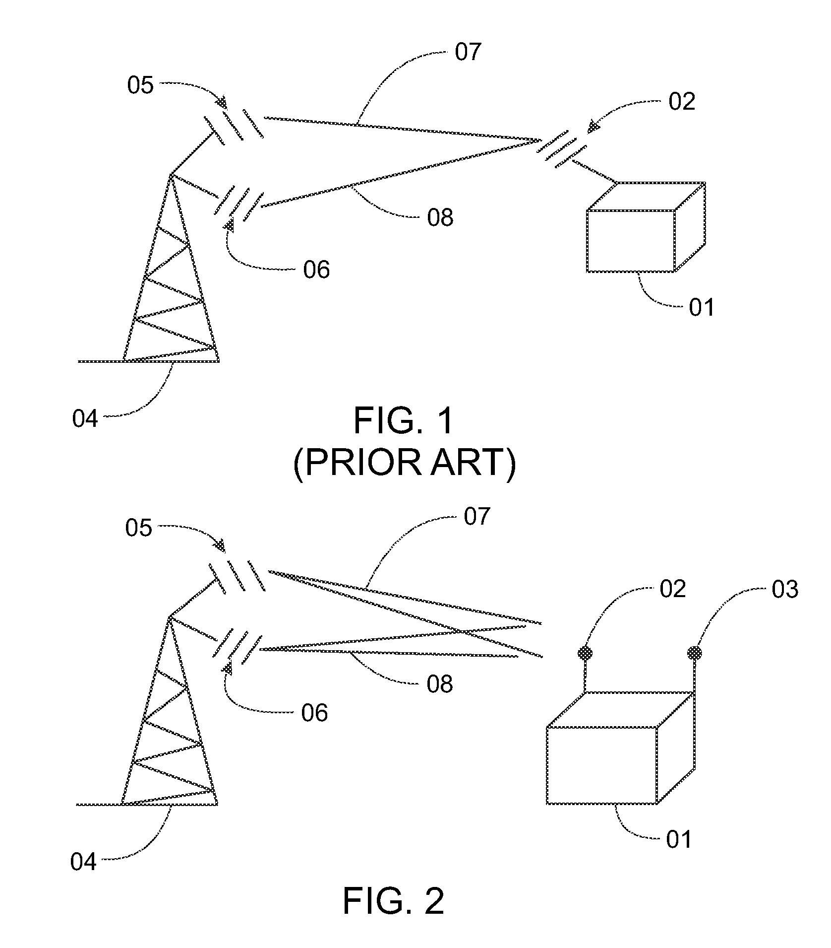
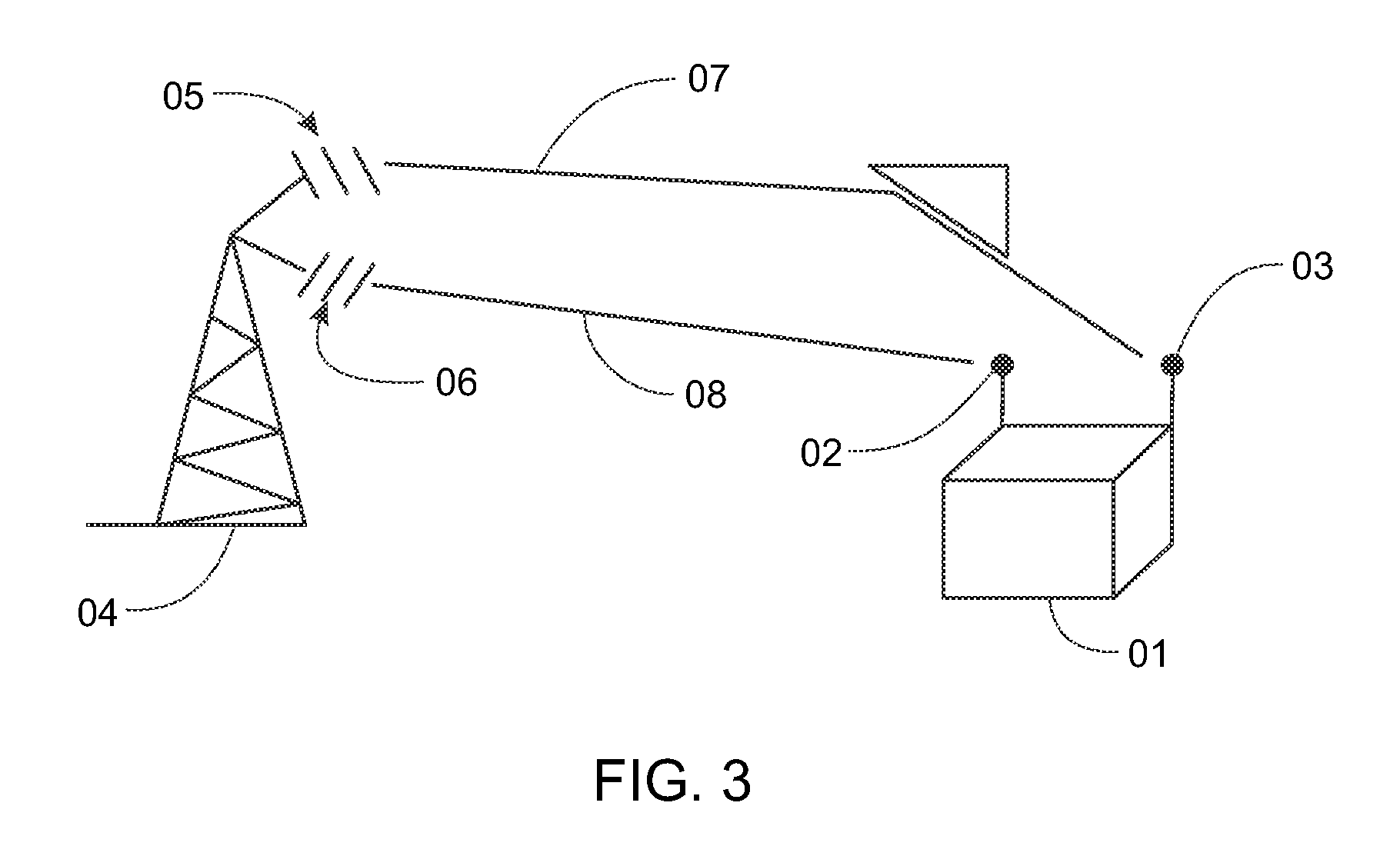
CROSS-REFERENCE TO RELATED APPLICATIONS[0001]The present application claims the benefit of Provisional Patent Application Ser. No. 61 / 458,344 filed Nov. 22, 2010, which is incorporated herein by reference.FIELD OF THE INVENTION[0002]The present invention relates to repeaters in networks. More particularly, it relates to repeaters in networks for multiple in / multiple out (“MIMO”) signals.BACKGROUND OF THE INVENTION[0003]Traditional 2G and 3G networks consist of one data stream, single input / single output (“SISO”) systems. Other networks, including, without limitation, Long Term Evolution (“LTE”) networks, utilize a MIMO system. They utilize two streams of data operating on the same channel. They rely on multipath effects to allow the network to disseminate the two streams of data independently to increase download and upload speeds. It is conventional wisdom in the signal processing community that repeaters do not work in these MIMO networks.[0004]As shown in FIG. 1, a repeater 01 wi...

Claims


Application Information

Patent Timeline
Patent Type & Authority Patents(United States)
IPC IPC(8): H04B15/00H04B7/14
CPCH04B7/0413H04B7/10H04B7/155
Inventor CRILLY, JR., WILLIAM, J.
Owner CELLULAR SPECIALTIES
Learn More