Self-lifting robotic device with load handling mechanism

a robotic device and load-handling technology, applied in the field of robotics, can solve problems such as reducing the throughput of storage systems

Inactive Publication Date: 2014-05-27
ATOOL TRADING LTD
View PDF42 Cites 26 Cited by
  • Summary
  • Abstract
  • Description
  • Claims
  • Application Information

AI Technical Summary

Benefits of technology

[0012]The platform may enable the grasping element to take the first load when the wheels are placed on the first rails, and to take the second load when the wheels are placed on the second rails.
[0017]The platform may enable the grasping element to take the first load when the platform is raised at a first vertical level with respect to the frame, and to enable the gripping element to take the third load when the platform is raised at a second vertical level with respect to the frame.

Problems solved by technology

Therefore, “bottlenecks” are created near the lifts, reducing the throughput of the storage system.

Method used


Image

  • Self-lifting robotic device with load handling mechanism
  • Self-lifting robotic device with load handling mechanism
  • Self-lifting robotic device with load handling mechanism

Examples


Embodiment Construction

[0032]The present disclosure will be made using exemplary embodiments described in the present disclosure. It will become apparent, however, that the concept of the disclosure is applicable to any robotic device movable in a vertical direction without an external lifting device.

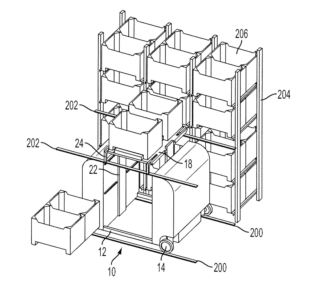
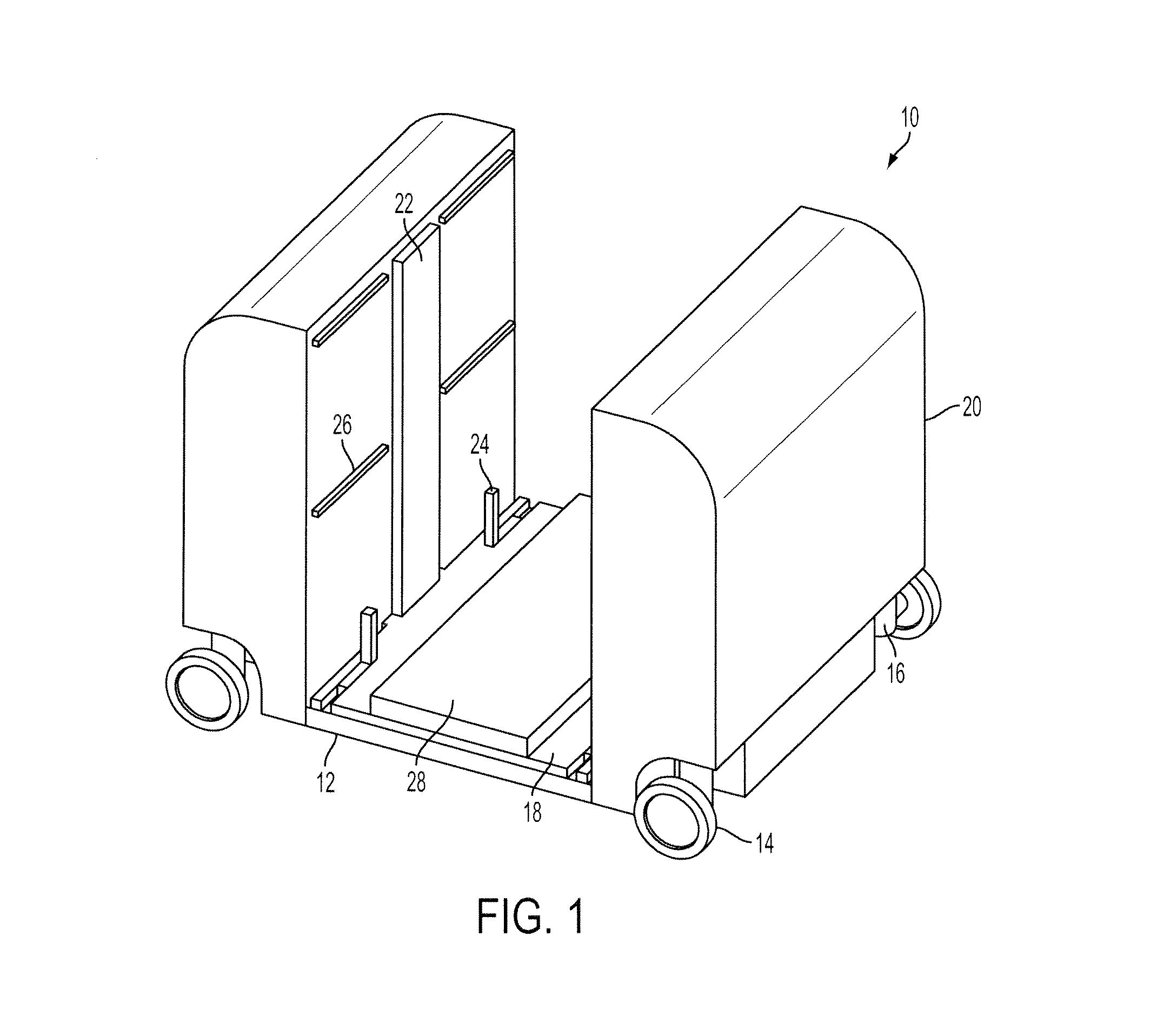
[0033]FIG. 1 shows an exemplary embodiment of a robotic device 10 of the present disclosure. The robotic device 10 may operate in a storage system arranged in a warehouse or retail facility. The storage system may have rails arranged in multiple rows corresponding to multiple levels of the storage system. Each row may include horizontal rails enabling the robotic device to move in horizontal directions. For example, the robotic device 10 may be configured for moving along a pair of horizontal rails. Also, as discussed below, the robotic device 10 has a self-lifting mechanism enabling the robotic device 10 to move between rails in a vertical direction.

[0034]In accordance with an exemplary embodiment, the robot...


PUM


Abstract

A robotic device movable in a vertical direction between rails arranged in multiple rows at various levels with respect to ground. The robotic device has a frame, wheels coupled to the frame for moving the frame along the rails, and a movable platform provided on the frame. The platform is configured for moving the frame in a vertical direction between first rails and second rails arranged above the first rails, and for placing onto the robotic device first and second loads arranged at different levels with respect to the ground.

Description

TECHNICAL FIELD[0001]This disclosure relates to robotics, and more particularly, to a self-lifting robotic device capable of handling loads while moving in a vertical direction without assistance of external lifts.BACKGROUND ART[0002]Storage or warehouse systems may include multi-level storage racks for storing loads, such as boxes, containers or pallets, at each of the multiple levels. Access to the stored loads may be provided by a shuttle system including multiple remotely controlled robotic devices or shuttles arranged on each level. The shuttles move back and forth in a single horizontal direction within one storage level to access stored goods arranged on the corresponding level and carry them.[0003]A lifting mechanism, such as a forklift, is provided to move loads in a vertical direction from the ground to the respective level of the storage rack or from the respective level to the ground. The forklift lifts newly arriving goods to the respective level and loads them to the s...

Claims


Application Information

Patent Timeline
Patent Type & Authority Patents(United States)
IPC IPC(8): B65G65/00B65G1/00
CPCB66F9/07B65G1/0492B21B41/00
Inventor RAZUMOV, SERGEY, N.
Owner ATOOL TRADING LTD
Why Eureka
Try Eureka