
Exercise arm and method of use

Active Publication Date: 2014-05-27
HOOLE RICHARD J
View PDF24 Cites 3 Cited by
  • Summary
  • Abstract
  • Description
  • Claims
  • Application Information

AI Technical Summary

Benefits of technology

The present invention relates to an exercise arm apparatus that can provide varying amounts of weight for an exerciser to add against the dip or chin they are performing. The apparatus includes an arm pivotally attached to at least one pivot point, an arm spindle on the arm, and weights that can be removably installed onto the arm spindle or from an elastic band connected to the exerciser's belt. The apparatus can also provide varying distances between the dip bar and belt attach points. The use of weights on the spindle and the use of existing weights make the apparatus inexpensive to manufacture. The technical effects of the invention include the ability to adjust the intensity of squats, dips, and chins being performed, enhance the exercise experience, and improve safety by eliminating heavy weights dangling from an exerciser's weight belt.

Problems solved by technology

If the knees slide forward or cave in then tension is taken from the hamstrings, hindering power on the ascent.
One of the hardest problems to solve associated with currently available squat, dip, and chin exercise apparatus is the inability to add resistance acting against the exerciser's upward motion during squats, dips and chins, thereby rendering the exercise more strenuous.
Currently available squat-dip-chin machines are either not weightable, or provide means to use weights to aid the exerciser during the exercise, thus rendering the exercise less strenuous.
While these weights have the effect of increasing the weight of the exerciser, and hence the strenuousness of the exercise, the procedure can be dangerous if the weights swing into the exerciser's limb(s), or if the exerciser were to slip off of the elevated foot support(s) and the heavy weights land on the exerciser's feet or other body part.

Method used


Image

  • Exercise arm and method of use
  • Exercise arm and method of use
  • Exercise arm and method of use

Examples


Embodiment Construction

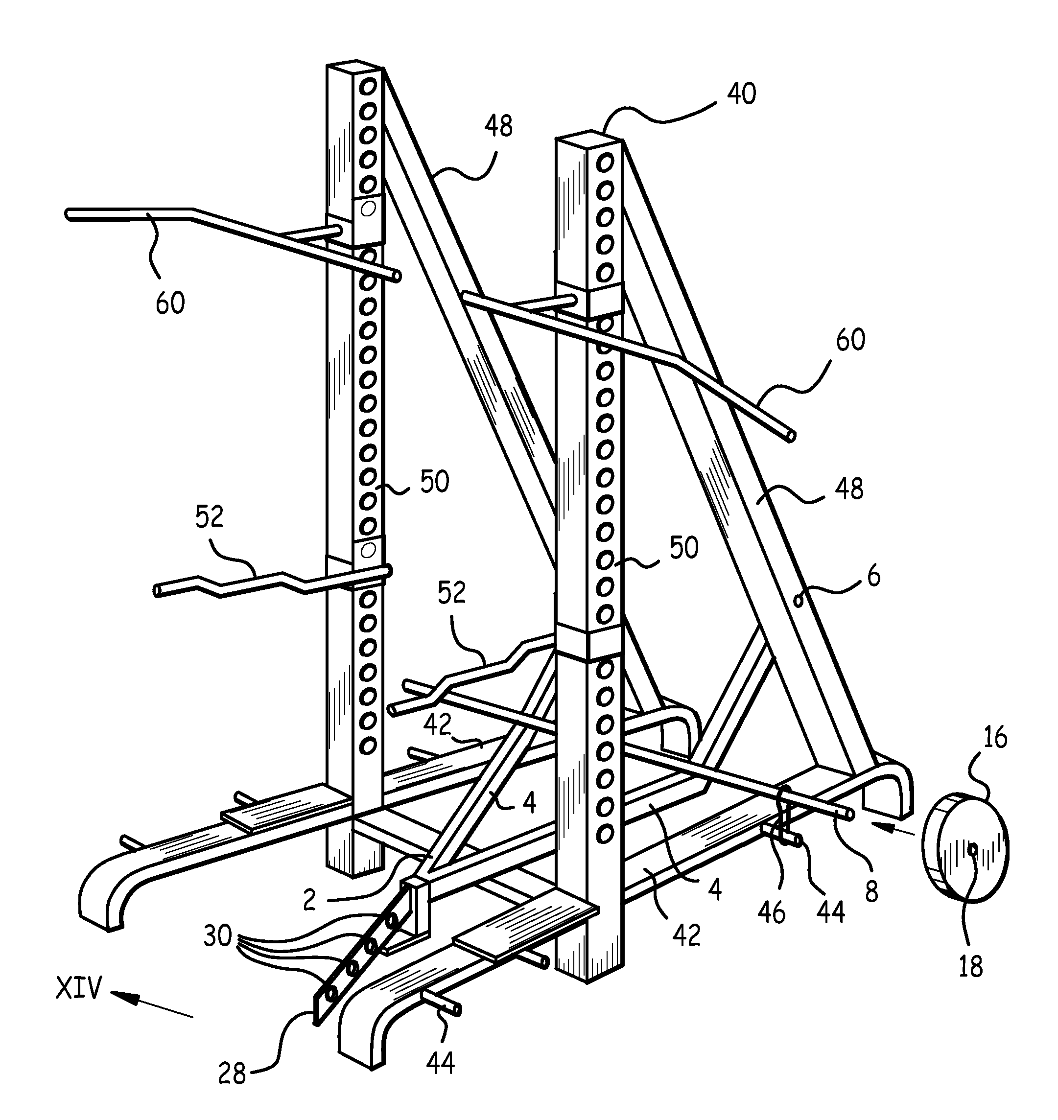
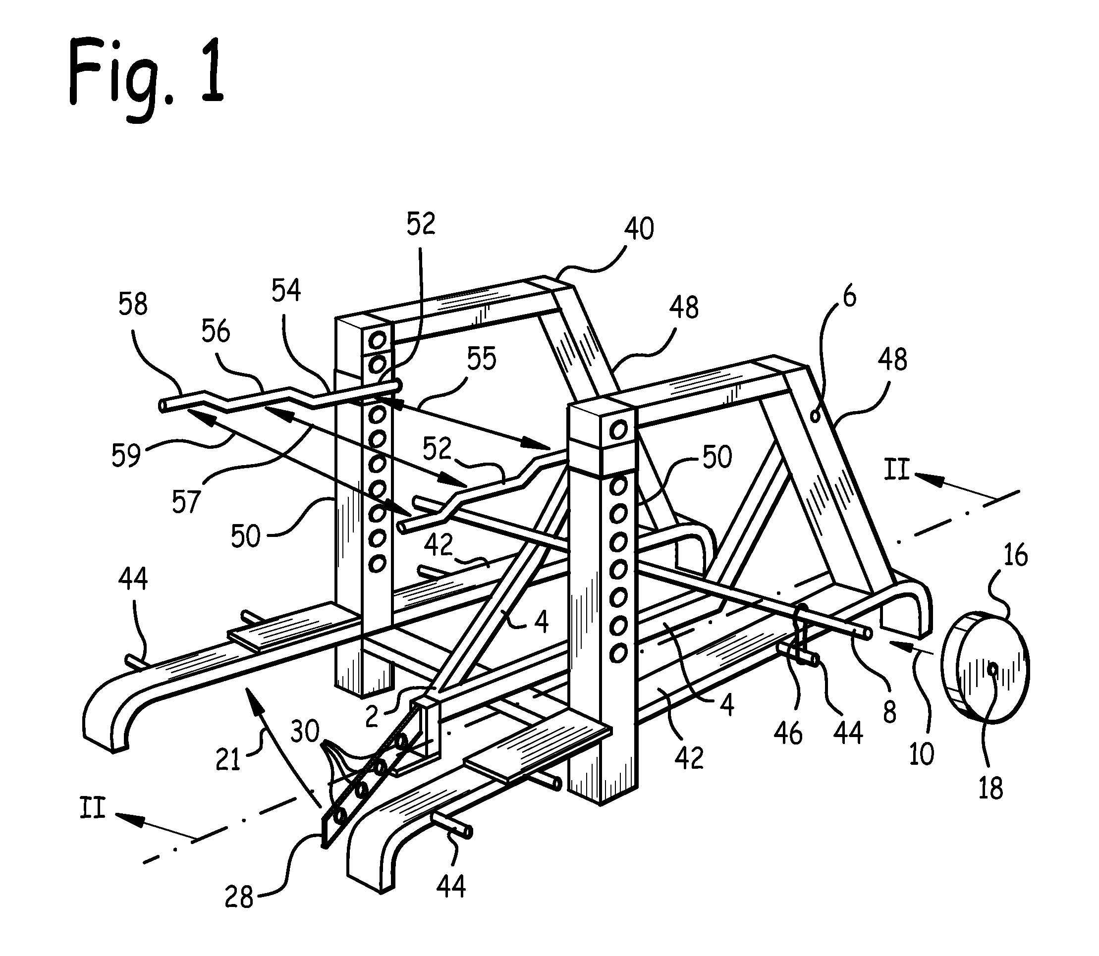
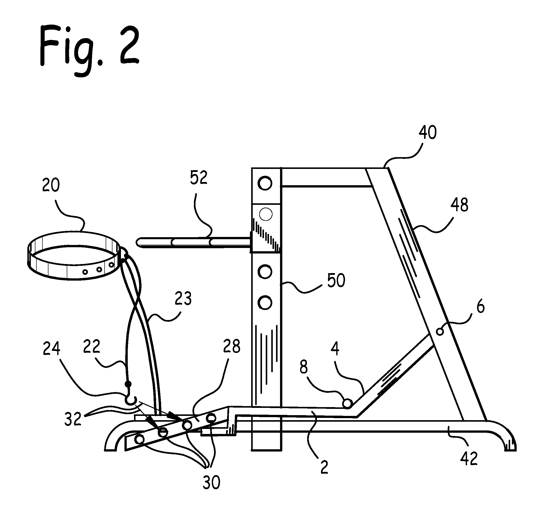
[0028]FIG. 1 is a right quarter side isometric view of an exercise arm 2 attached to frame 40 having dip bars 52. FIG. 2 is a right side cross-sectional view of an exercise arm apparatus with its arm 2 in the resting position, taken at section II-II of FIG. 1. Frame 40 comprises at least one rear upright 48 rigidly attached to base 42, rising upwards from base 42. Base 42 may be any appropriately stable base to which rear uprights 48 and front uprights 50 may be attached. Exercise arm 2 comprises at least one finger 4 rotatably attached to a corresponding rear upright 48 at a pivot point 6.

[0029]Exercise arm 2 further comprises spindle 8 rigidly attached to finger 4. One or more weights 16 having weight apertures 18 sized to slidably admit spindle 8 may be emplaced on spindle 20 by sliding spindle 20 through weight aperture 18 as indicated by arrow 10 in FIG. 1.

[0030]When a desired number of weights 16 have been emplaced on spindle 8, an exerciser wearing belt 20 may attach belt hoo...


PUM


Abstract

An exercise arm apparatus and method of use. The exercise arm comprises at least one finger, a spindle attached to the finger, and weights sized to reside on the spindle. One end of the exercise arm is rotatably attached at a pivot point to a frame or to a vertical surface; a belt is attached to an opposite end of the exercise arm by means of a belt line. Where the exercise arm is rotatably attached to a frame, dip bars and chin bars are disclosed wherein an exerciser may perform dips and chins. Upward motion by an exerciser wearing the belt is impeded by spindle weights, a belt elastic attached at one end to the belt and at an opposite end to the exercise arm, and / or an elastic member attached at one end to the frame and at an opposite end to the exercise arm.

Description

CLAIM FOR PRIORITY[0001]This application is a continuation-in-part of pending U.S. patent application Ser. No. 11 / 811,920 filed Jun. 11, 2007, U.S. patent application Ser. No. 12 / 156,487 filed Jun. 2, 2008, and Ser. No. 12 / 658,855 filed Feb. 16, 2010 and claims the benefit of the earlier filing date of these applications.BACKGROUND OF THE INVENTION[0002]1. Field of the Invention[0003]This invention relates to exercise machines, and in particular to an exercise arm apparatus and method of use.[0004]2. Background of the Invention[0005]The exercise arm apparatus and method of use described herein may be used for squat, dip, and chin exercises.[0006]Squats exercise the muscles of the thighs, hips and buttocks, and also strengthen the bones, ligaments and tendons throughout the lower body. For this reason, squats are regarded as an important exercise for strength-increase in the legs and buttocks.[0007]Ideally, a squat exercise series begins from a standing position. The knees and hips a...

Claims


Application Information

Patent Timeline
IPC IPC(8): A63B21/00
CPCA63B23/12A63B2225/093A63B21/0435A63B23/1218A63B21/062A63B21/0552A63B2023/0411A63B21/0615A63B2021/169A63B21/1419A63B23/1227A63B21/169A63B21/4009
Inventor HOOLE, RICHARD, J.
Owner HOOLE RICHARD J
Learn More