Hold-up time extension circuit for a power converter

a technology of extension circuit and power converter, which is applied in the direction of electric variable regulation, process and machine control, instruments, etc., can solve the problems of unaddressed need in the ar

Inactive Publication Date: 2014-05-27
DELTA ELECTRONICS (SHANGHAI) CO LTD
View PDF3 Cites 25 Cited by
  • Summary
  • Abstract
  • Description
  • Claims
  • Application Information

AI Technical Summary

Benefits of technology

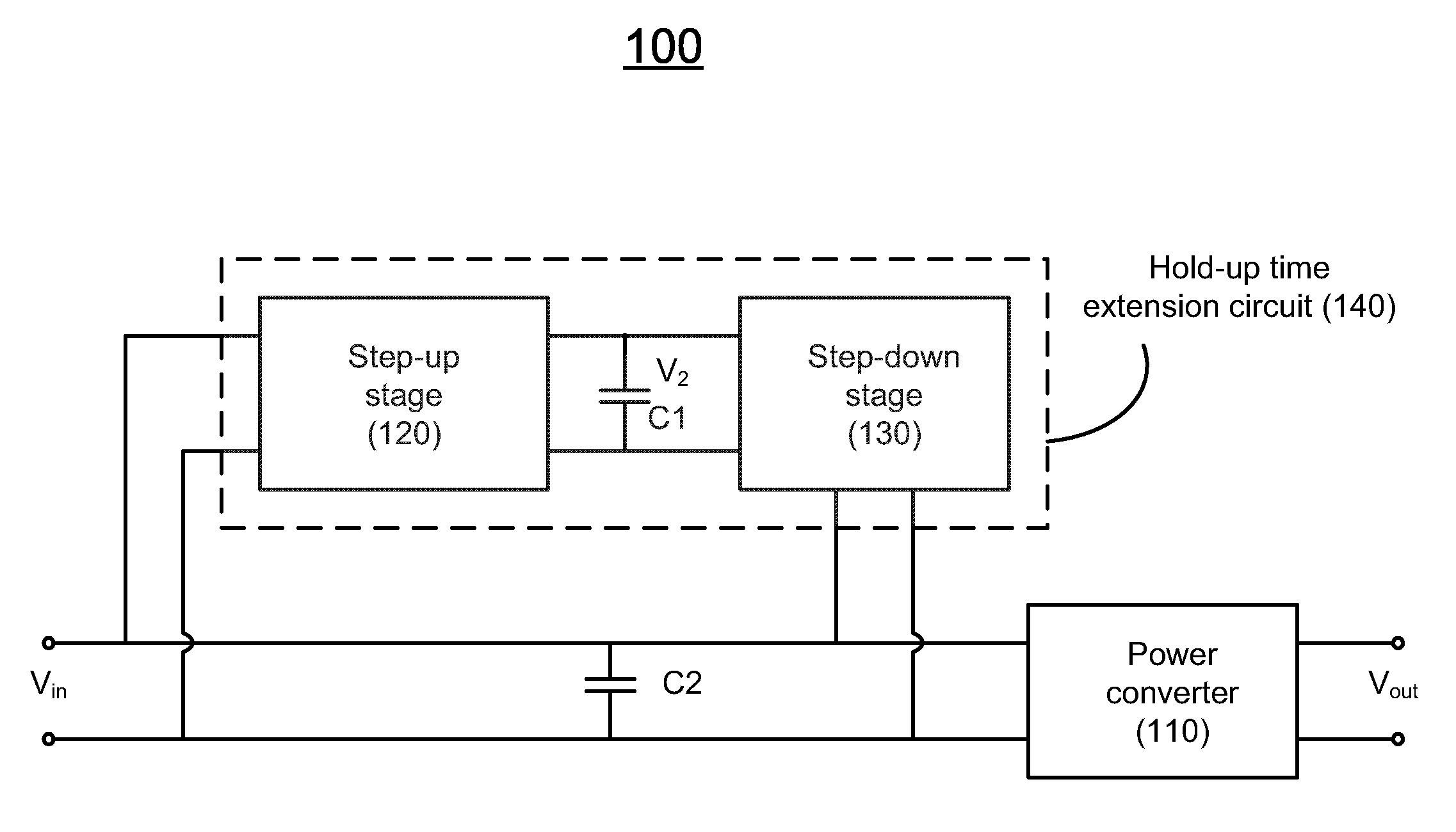
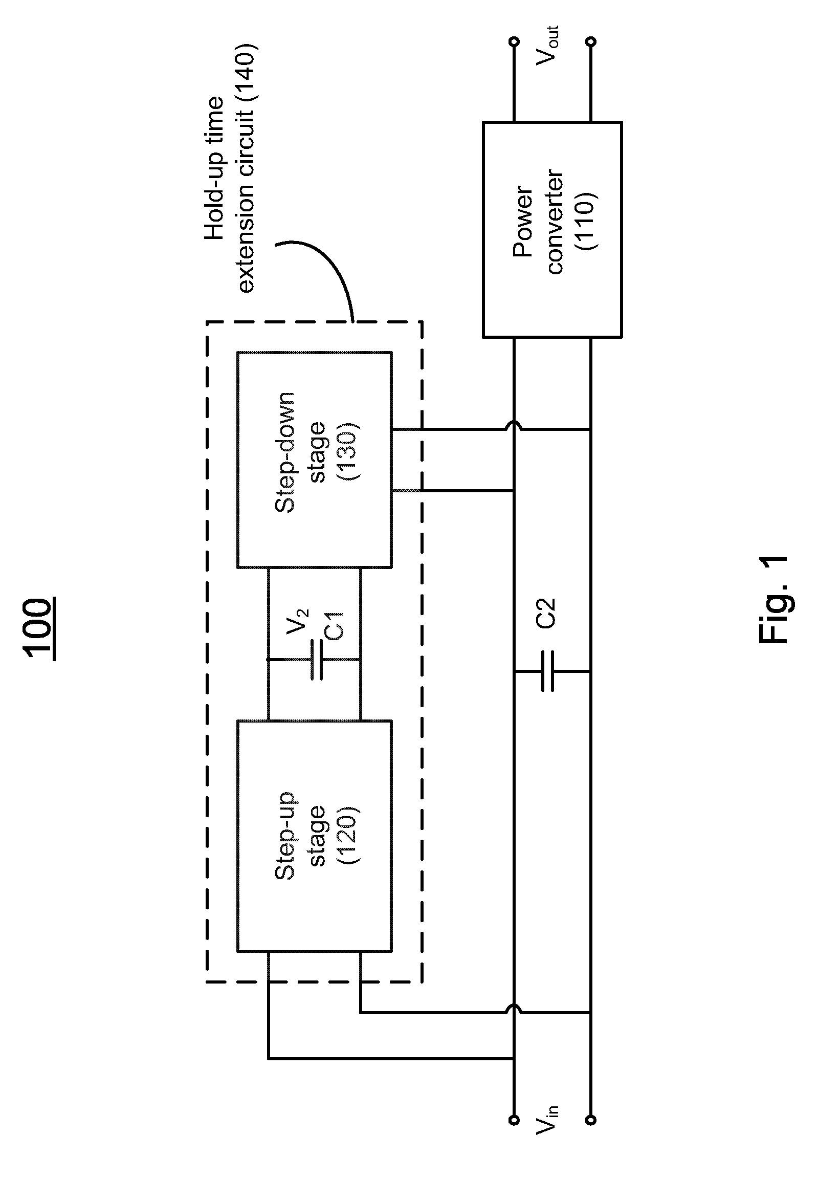
[0027]FIG. 1 shows a schematic diagram of a power system including a power converter and a hold-up time extension circuit according to one embodiment of the present invention;

Problems solved by technology

Therefore, a heretofore unaddressed need exists in the art to address the aforementioned deficiencies and inadequacies.

Method used


Image

  • Hold-up time extension circuit for a power converter
  • Hold-up time extension circuit for a power converter
  • Hold-up time extension circuit for a power converter

Examples


Embodiment Construction

[0034]The present invention will now be described more fully hereinafter with reference to the accompanying drawings, in which exemplary embodiments of the invention are shown. This invention may, however, be embodied in many different forms and should not be construed as limited to the embodiments set forth herein. Rather, these embodiments are provided so that this disclosure will be thorough and complete, and will fully convey the scope of the invention to those skilled in the art. Like reference numerals refer to like elements throughout.

[0035]The terminology used herein is for the purpose of describing particular embodiments only and is not intended to be limiting of the invention. As used herein, the singular forms “a”, “an” and “the” are intended to include the plural forms as well, unless the context clearly indicates otherwise. It will be further understood that the terms “comprises” and / or “comprising,” or “includes” and / or “including” or “has” and / or “having” when used he...


PUM


Abstract

A power system has a power converter adapted for converting a first input voltage at an input thereof to a first output voltage at an output thereof, and a hold-up time extension circuit comprising a step-up stage and a step-down stage coupled to each other via a first energy-storage capacitor, where an input of the step-up stage is coupled to the input of the power converter, an output of the step-up stage is coupled to an input of the step-down stage, and an output of the step-down stage is coupled to the input of the power converter. The step-up stage is adapted for converting the first input voltage of the power converter to a second output voltage, and the step-down stage is adapted for converting the second output voltage of the step-up stage to the input voltage of the power converter.

Description

CROSS-REFERENCE TO RELATED PATENT APPLICATION[0001]This application claims priority to and the benefit of, pursuant to 35 U.S.C. §119(a), Chinese patent application No. 201110208372.X, filed Jul. 25, 2011, entitled “HOLD-UP TIME EXTENSION CIRCUIT FOR A POWER CONVERTER”, by Gang Liu and Liang He, the content of which is incorporated herein by reference in its entirety.[0002]Some references, which may include patents, patent applications and various publications, are cited and discussed in the description of this invention. The citation and / or discussion of such references is provided merely to clarify the description of the present invention and is not an admission that any such reference is “prior art” to the invention described herein. All references cited and discussed in this specification are incorporated herein by reference in their entireties and to the same extent as if each reference were individually incorporated by reference.FIELD OF THE INVENTION[0003]The present inventio...

Claims


Application Information

Patent Timeline
Patent Type & Authority Patents(United States)
IPC IPC(8): H02M3/158
CPCH02M3/335H02M2001/0096Y10T307/516H02M1/0096
Inventor LIU, GANGHE, LIANG
Owner DELTA ELECTRONICS (SHANGHAI) CO LTD
Why Eureka
Try Eureka