Device and method for predistorting a transmission signal to be transmitted via a nonlinear transmission path

a transmission signal and nonlinear transmission technology, applied in the direction of transmission/receiver shaping networks, modulated carrier systems, power amplifiers, etc., can solve the problems of increased nonlinearity, difficulty in matching amplifiers to load, and inaccessible access, so as to reduce spurious emission, improve linearization, and reduce costs

Inactive Publication Date: 2007-01-30
FRAUNHOFER GESELLSCHAFT ZUR FOERDERUNG DER ANGEWANDTEN FORSCHUNG EV
View PDF28 Cites 19 Cited by
  • Summary
  • Abstract
  • Description
  • Claims
  • Application Information

AI Technical Summary

Benefits of technology

[0056]The present invention provides a number of advantages over known predistortion systems. For one thing, all the signal processing can be performed digitally, so that there are no component tolerance or adjustment problems. Also, there is no need to tamper with the high-frequency part, i.e. the power amplifier or the bandpass filter which follows this. The reduced spurious emission achieved by the present invention means that substantial savings can be made as regards the power amplifier and its power supply since both can be made smaller. In addition to this, less stringent demands are made on the bandpass filter, which again lowers the costs. Compared with classical linearization methods substantially higher linearization gains in the order of 20 dB can be achieved with the present invention, as opposed to linearization gains of 5 to 8 dB with classical linearization methods.

Problems solved by technology

The amplitude error of the amplifier is thus compensated for by adjusting its operating point, which has the disadvantage that the operating point parameters of the amplifier have to be changed continually, which can make it very difficult to match the amplifier to a load since changing the operating point normally automatically entails a different (complex) transformation relationship for the output resistance.
In many cases such access is not available since linearization can only be performed within the closed system of the power output stage.
In the case of analog predistortion of the high-frequency signal there is the problem of having to synthesize a suitable characteristic from nonlinear components which are subject to individual differences, temperature drift, ageing, etc.
Ageing of the components may result in increased nonlinearity.
As a consequence of the high amplification there is also a strong tendency for the whole arrangement to oscillate if the feedback parameters are not determined precisely.
The noise behaviour of the output stage is also seriously degraded by the negative feedback since this introduces uncorrelated noise into the amplifier stage.
The linearization demands made on the correction signal are high, which means that technically advanced, costly power amplifiers must be used in a circuit which performs linearization according to the feedforward method.
It has turned out, however, that complete compensation is scarcely achievable with this system and furthermore interference segments still remain in the immediate neighbourhood of the useful channel of the transmission signal.
As soon as the amplifier is so strongly driven for a short time that it acts as a limiter, the predistortion becomes ineffective.
The feedforward methods which have also been described represent a disturbance-variable insertion in the sense of control engineering, as already mentioned, a disadvantage being that an amplifier with a performce almost equal to that of the amplifier to be linearized is needed to generate the correction signal.
For input signals with a high crest factor, which occur e.g. in multicarrier methods, the known methods are ineffective since the power amplifier momentarily enters the limiting region.

Method used


Image

  • Device and method for predistorting a transmission signal to be transmitted via a nonlinear transmission path
  • Device and method for predistorting a transmission signal to be transmitted via a nonlinear transmission path
  • Device and method for predistorting a transmission signal to be transmitted via a nonlinear transmission path

Examples


Embodiment Construction

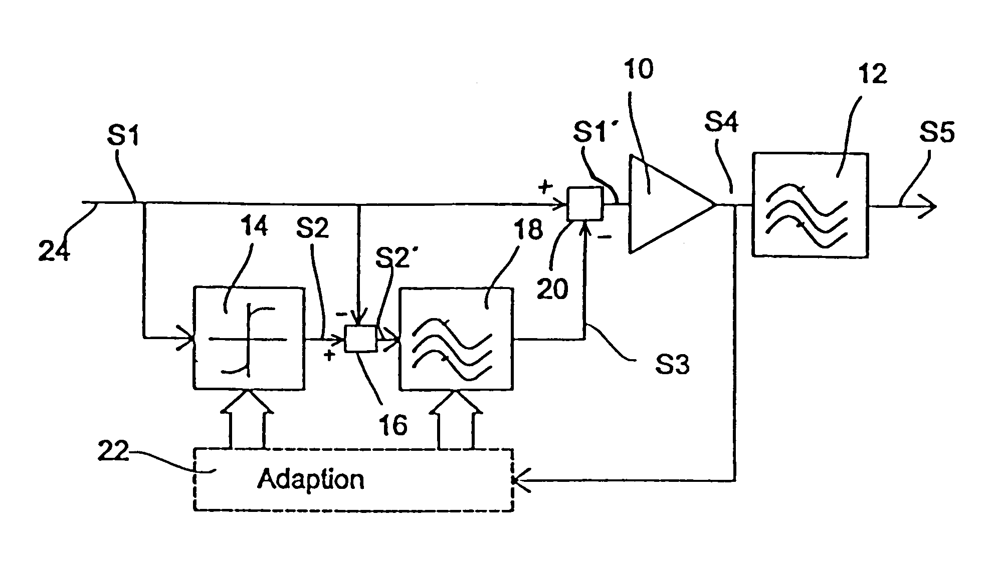
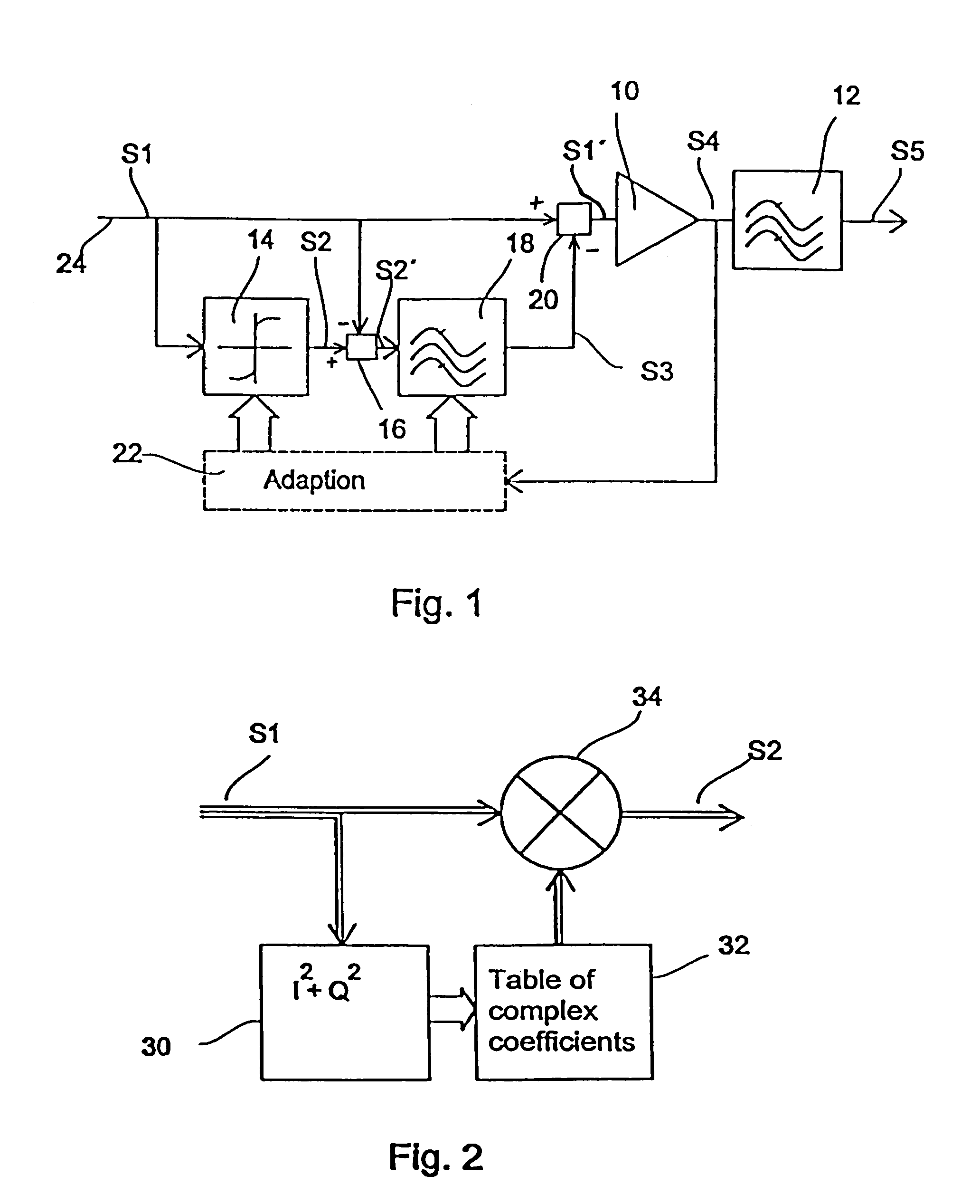
[0062]A preferred embodiment of the present invention will now be described in terms of a transmitter which features a high-frequency power amplifier. It is clear, however, that the present invention can also be employed to predistort signals transmitted over other nonlinear transmission paths.

[0063]FIG. 1 shows a transmitter which might be used e.g. for digital broadcasting. An input signal S1, which might be a multicarrier signal with a non-constant envelope, is fed into the transmitter. Without predistortion this input signal S1 would be fed directly into a power amplifier 10, which is followed by a narrow bandpass filter 12. However, in order to compensate for nonlinearities of the power amplifier 10, which represents a nonlinear transmission path, the input signal S1 is first predistorted. The input signal S1 is therefore first fed into an emulator 14 which emulates the nonlinear behaviour of the power amplifier 10, i.e. an AM / AM and an AM / PM conversion. The resulting signal S2...


PUM


Abstract

A device for predistorting a transmission signal to be transmitted over a nonlinear transmission path comprises an estimator for determining an error signal depending on the transmission signal and a previously registered transfer characteristic of the nonlinear transmission path. The error signal represents an estimate of an error generated due to the nonlinearity of the trans-mission path. A time-dispersive element is provided to produce a correction signal by a temporal extension of the error signal. A combiner is provided to combine the transmission signal and the correction signal. As a result of the temporal extension of the error signal, an error signal segment in the frequency spectrum of a transmission signal transmitted by the nonlinear transmission path is shifted away from the useful frequency range of the transmission signal.

Description

BACKGROUND OF THE INVENTION[0001]1. Field of the Invention[0002]The present invention relates to a device and a method for predistorting signals to be transmitted over a nonlinear transmission path in such a way that the influence of interference segments on the useful part of the signal transmitted over the nonlinear transmission path can be optimized. The present invention may preferably be employed in transmitters for digital broadcasting, which are supplied with signals composed of a number of single carriers and which result in a non-constant envelope of a high-frequency carrier signal. It is particularly in the case of such signals that the nonlinearity of the power amplifier of an output stage of the transmitter gives rise to undesirable frequencies in the signal at the output of the power amplifier which disturb neighbouring frequency channels.[0003]If modulation methods which lead to a non-constant envelope for the high-frequency carrier signal are used in e.g. a wireless c...

Claims


Application Information

Patent Timeline
Patent Type & Authority Patents(United States)
IPC IPC(8): H04K1/02H04L25/03H04L25/49H03F1/32H03F3/24H04L27/26H04L27/36
CPCH03F1/3247H03F1/3252H03F3/24H04L27/368H04L27/2614H04L27/2626H03F2200/102
Inventor PERTHOLD, RAINERHOFMAN, MAXIMILIANROGALSKY, INGOGERHAFUSER, HEINZ
Owner FRAUNHOFER GESELLSCHAFT ZUR FOERDERUNG DER ANGEWANDTEN FORSCHUNG EV
Why Eureka
Try Eureka