Friction spot joining method

a friction spot and joining method technology, applied in metal-working equipment, welding equipment, manufacturing tools, etc., can solve the problems of difficult to achieve the desired nugget, and achieve the effect of suppressing the elongation of the time required for joining, suppressing the lowering of the corrosion resistance of the second metal-coated, and promoting the generation of frictional hea

Inactive Publication Date: 2008-03-20
MAZDA MOTOR CORP
View PDF6 Cites 19 Cited by
  • Summary
  • Abstract
  • Description
  • Claims
  • Application Information

AI Technical Summary

Benefits of technology

[0033]In the present invention, a plurality of steel plates are overlaid in such a fashion that at least one of the two steel plates located on the respective sides in the overlaying direction is the first non-coated steel plate, and the rotary tool is rotated and allowed to press the to-be-joined part of the plurality of overlaid steel plates from the first non-coated steel plate side, so that the rotary tool hardly slips to promote generation of frictional heat, thereby suppressing el

Problems solved by technology

In the above method, however, if three or more to-be-joined steel plates including a mild steel plate and

Method used


Image

  • Friction spot joining method
  • Friction spot joining method
  • Friction spot joining method

Examples


working examples

[0058]Working Examples of the present invention will be described below.

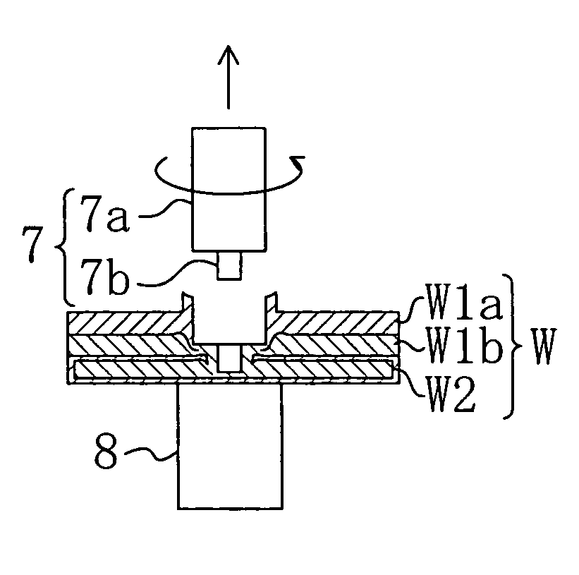
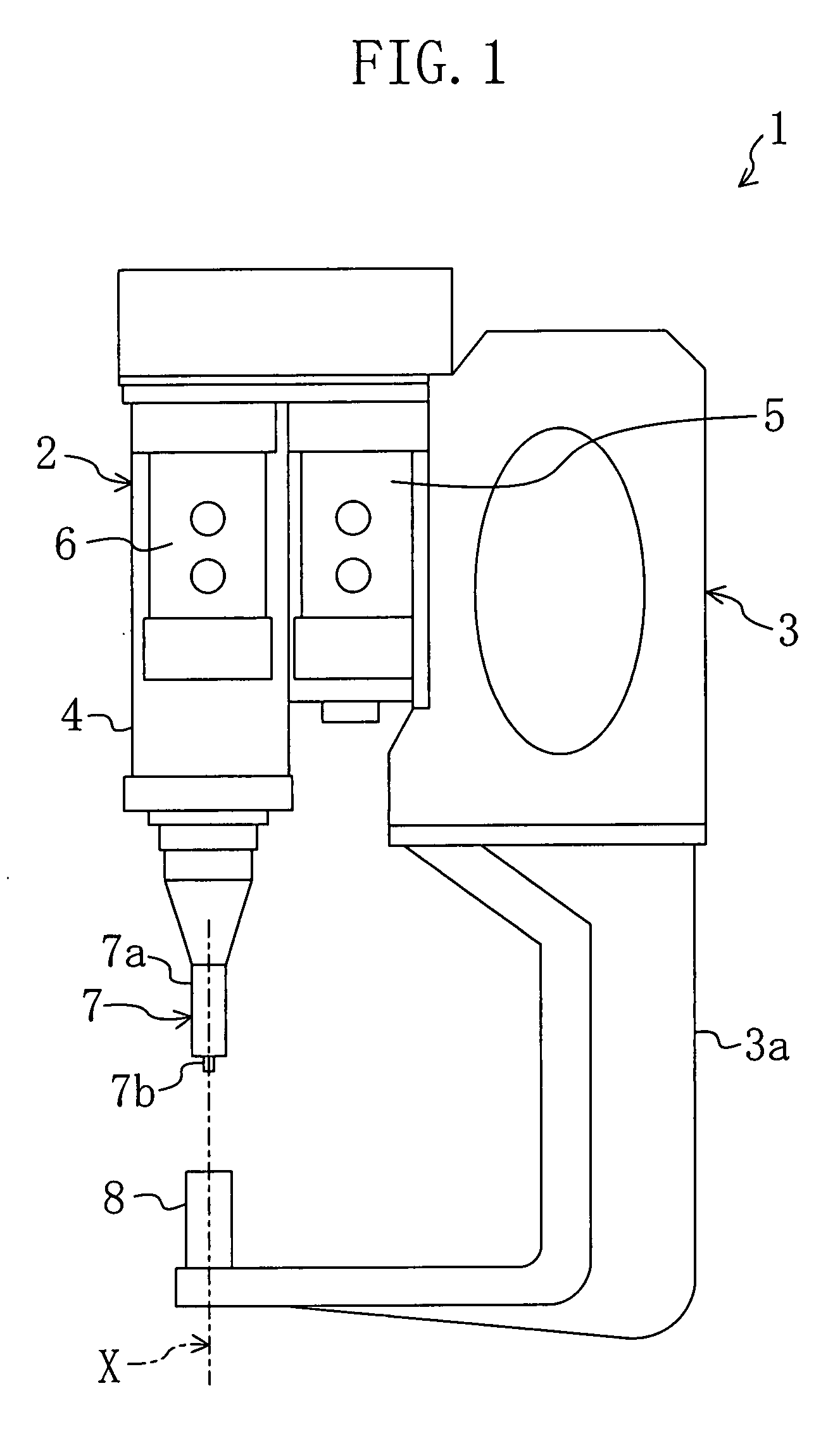
[0059](Joining Unit)

[0060]A stationary pressure unit having a servo motor as the pressure shaft motor was employed as the joining unit.

[0061]A ceramic-made rotary tool was used as the rotary tool. The diameter of the shoulder part of the rotary tool was 10 mm. The diameter and the length of the pin of the rotary tool were 3 mm and 1.27 mm, respectively.

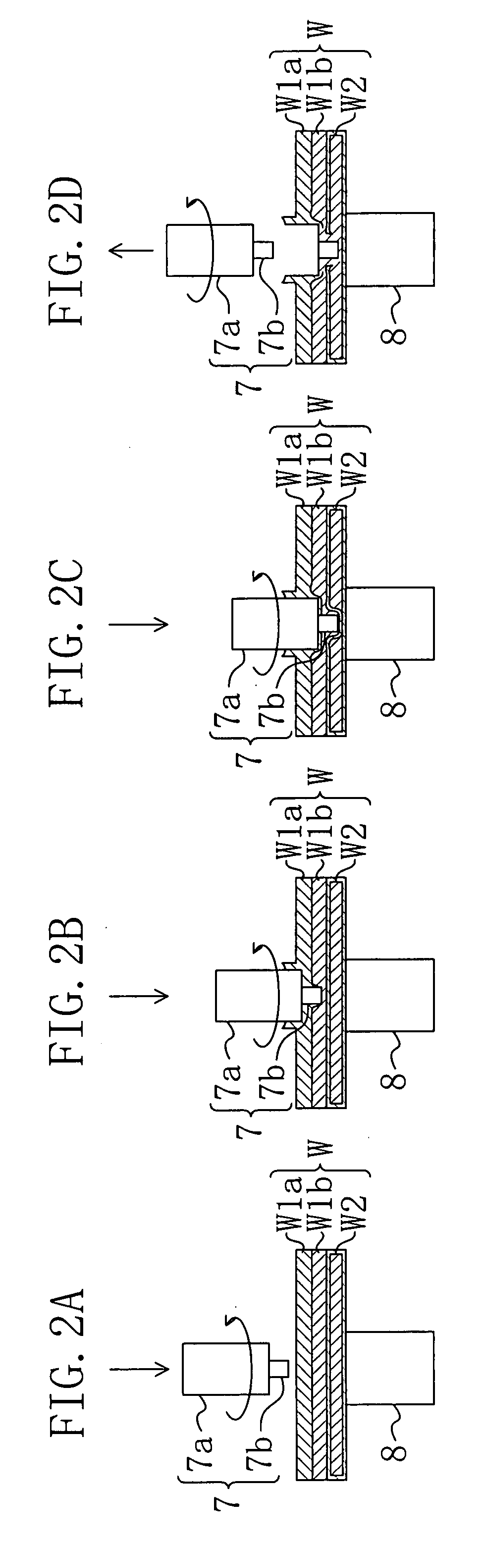
[0062](Steel Plates)

[0063]High-tensile steel plates (JIS 3135 SPFC980Y) on a 980 MPa level having a thickness of 1.0 mm were used as the first steel plates. The compositions of the first steel plates are indicated in FIG. 3.

[0064]A mild steel plate on a 270 MPa level was used as the second steel plate. The second steel plate was zinc-coated and was subjected to an alloying process to obtain a galvaneal steel plate having a coating weight of 55 g / m2 and a thickness of 0.7 mm. The melting point of the alloyed hot dip zinc coating, which depends on the content ratio ...


PUM

PropertyMeasurementUnit
Timeaaaaaaaaaa
Percent by massaaaaaaaaaa

Abstract

A plurality of steel plates including at least one first non-coated steel plate and at least one metal-coated steel plate are prepared. The plurality of steel plates are overlaid in such a fashion that at least one of the two steel plates located on the respective sides in the overlaying direction is the first non-coated steel plate. A rotary tool is rotated and allowed to press a to-be-joined part of the plurality of overlaid steel plates from the first non-coated steel plate side to friction-spot-join the to-be-joined part in a solid state by causing plastic flow at the to-be-joined part by generated frictional heat. Whereby, both elongation of time required for joining and lowering of the corrosion resistance of the metal-coated steel plate are suppressed.

Description

FIELD OF THE INVENTION[0001]The present invention relates to a friction spot joining method.BACKGROUND ART[0002]As a method of spot-joining a plurality of steel plates overlaid in the thickness direction thereof as a work piece used for, for example, a car body of an automobile, a resistance spot welding method has been well known conventionally in which a to-be-joined part of the plurality of overlaid steel plates is clipped between copper electrodes and are conducted to generate resistance heat by the conduction so that the to-be-joined part is joined by the resistance heat.[0003]As steel plates for car bodies, mild steel has been employed up to now while there is a growing trend toward employment of high-tensile steel for weight reduction of automobiles.[0004]In the above method, however, if three or more to-be-joined steel plates including a mild steel plate and a high-tensile steel plate have different inherent resistances, it is difficult to attain a desired nugget.[0005]Recen...

Claims


Application Information

Patent Timeline
IPC IPC(8): B23K20/12
CPCB23K20/1265
Inventor GENDOU, TOSHIYUKI
Owner MAZDA MOTOR CORP
Why Eureka
Try Eureka