Paint, retardation element, display device, method for manufacturing retardation element

a retardation element and display device technology, applied in the direction of optical elements, instruments, coatings, etc., can solve the problems of reducing yield advantageously, affecting the appearance of the alignment film, and the restraining force of the alignment film is not likely to work, so as to reduce the black luminance in the black area, the number of bright points, and the effect of reducing the number of slight alignment defects

Active Publication Date: 2014-05-27
DEXERIALS CORP
View PDF15 Cites 2 Cited by
  • Summary
  • Abstract
  • Description
  • Claims
  • Application Information

AI Technical Summary

Benefits of technology

[0010]Japanese Patent No. 4385997 has disclosed that a small amount of an acrylic copolymer having a fluorine group is added to a liquid crystal paint. By this technique, since the acrylic copolymer moves to the vicinity of an interface with air by a fluorine effect, the liquid-liquid crystal transition temperature in the vicinity of the interface with air decreases, so that the alignment restraining force of an alignment film effectively works even in the vicinity of the interface with air. As a result, the number of alignment defects can be reduced. However, in this case, it is necessary to prepare an acrylic copolymer having controlled molecular weight and structure, and hence there is a problem in terms of manufacturing cost and productivity.
[0025]In addition, in the case in which a monomer which has an isocyanuric ring structure having at least three functional groups is used as the non-liquid crystal monomer in the paint according to an embodiment of the present disclosure, compared with the case in which another monomer is used as the non-liquid crystal monomer, when the weight content of the non-liquid crystal monomer and the drying temperature are respectively set equal to those of the above comparative case, the number of bright points contained in an area of 3.0×105 μm2 can be reduced or can be made zero. In addition, when the monomer which has an isocyanuric ring structure having at least three functional groups is used as the non-liquid crystal monomer, the number of slight alignment defects which may not be observed by an optical microscope can also be significantly reduced as well as the number of bright points. Hence, for example, in the case in which the monomer which has an isocyanuric ring structure having at least three functional groups is used as the non-liquid crystal monomer, when the content of the non-liquid crystal monomer is set to 5 to 10 percent by weight on a weight ratio to that of the liquid crystal monomer, the number of bright points contained in 1 μm2 can be made zero, and furthermore, the number of slight alignment defects which may not be observed by an optical microscope moreover can also be significantly reduced. As a result, the black luminance in the black area can be significantly reduced.

Problems solved by technology

However, among the liquid crystal monomer molecules contained in the liquid crystal layer, the alignment restraining force of the alignment film is not likely to work on liquid crystal monomer molecules located far from the alignment film.
Therefore, alignment defects are liable to occur, and the yield is advantageously liable to decrease.
However, when a polyfunctional liquid crystal monomer is used as a liquid crystal monomer, the temperature at which the liquid crystal layer shows a liquid crystal phase is increased so as to induce thermal polymerization, and as a result, the uniformity of the liquid crystal alignment is disadvantageously degraded.
As a result, decrease in mechanical strength of the sheet and degradation in dimensional stability and retardation caused by heat disadvantageously occur.
In addition, Japanese Unexamined Patent Application Publication No. 2010-83781 has disclosed a curable liquid crystal material which can ensure mechanical strengths of a sheet while decreasing the temperature at which the liquid crystal phase is obtained; however, this curable liquid crystal material is a special material and has problems in terms of manufacturing cost and productivity.
However, even if this additive is used, it is practically difficult to ideally control the alignment of the liquid crystal molecules in the vicinity of the interface with air.
As a result, problems in that dimensional stability and retardation are degraded by heat occur.

Method used


Image

  • Paint, retardation element, display device, method for manufacturing retardation element
  • Paint, retardation element, display device, method for manufacturing retardation element
  • Paint, retardation element, display device, method for manufacturing retardation element

Examples


first embodiment

1. First Embodiment

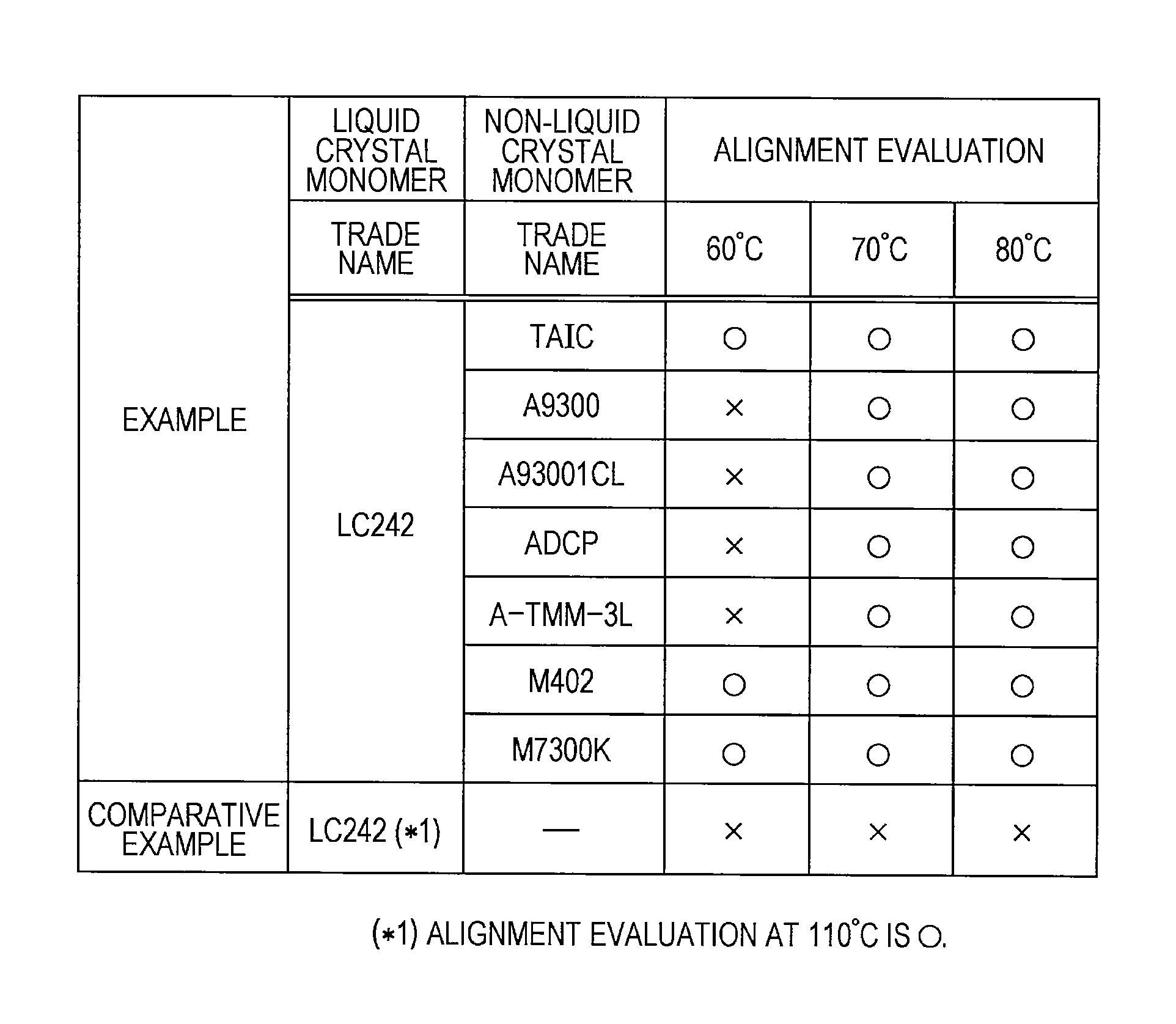
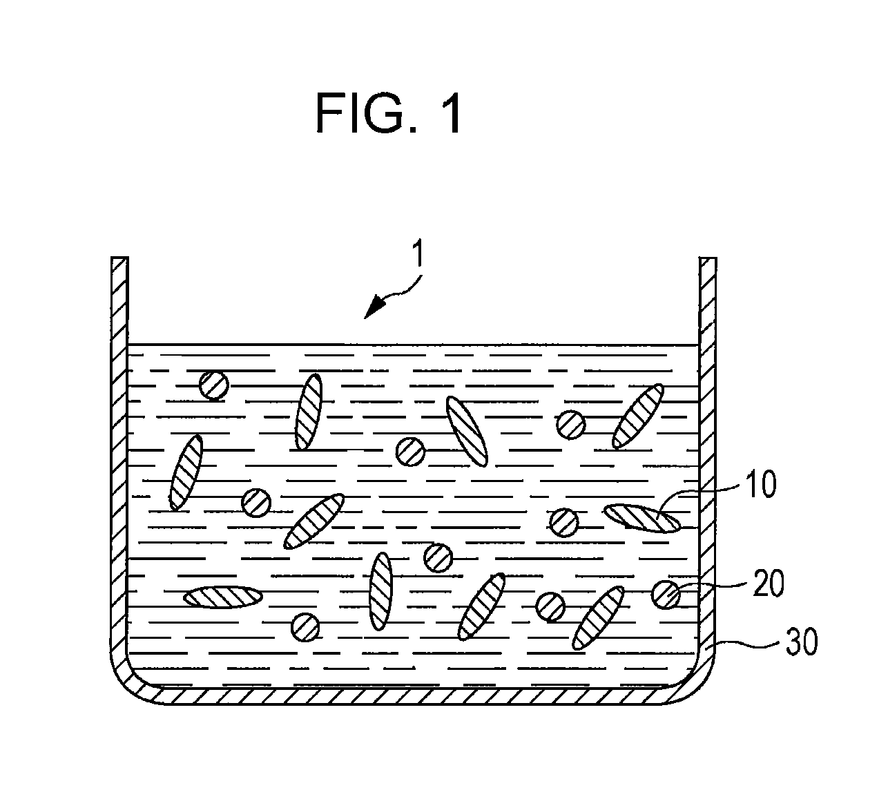
[0054]First, a paint 1 according to a first embodiment of the present disclosure will be described. As shown in FIG. 1, the paint 1 is, for example, a liquid material which can be accommodated in a container 30 and contains a liquid crystal monomer 10 and a non-liquid crystal monomer 20. In addition, the paint 1 may also contain materials other than the liquid crystal monomer 10 and the non-liquid crystal monomer 20 and, for example, may contain an initiator, a surfactant, a polymerization inhibitor, a plasticizer, and / or a viscosity modifier.

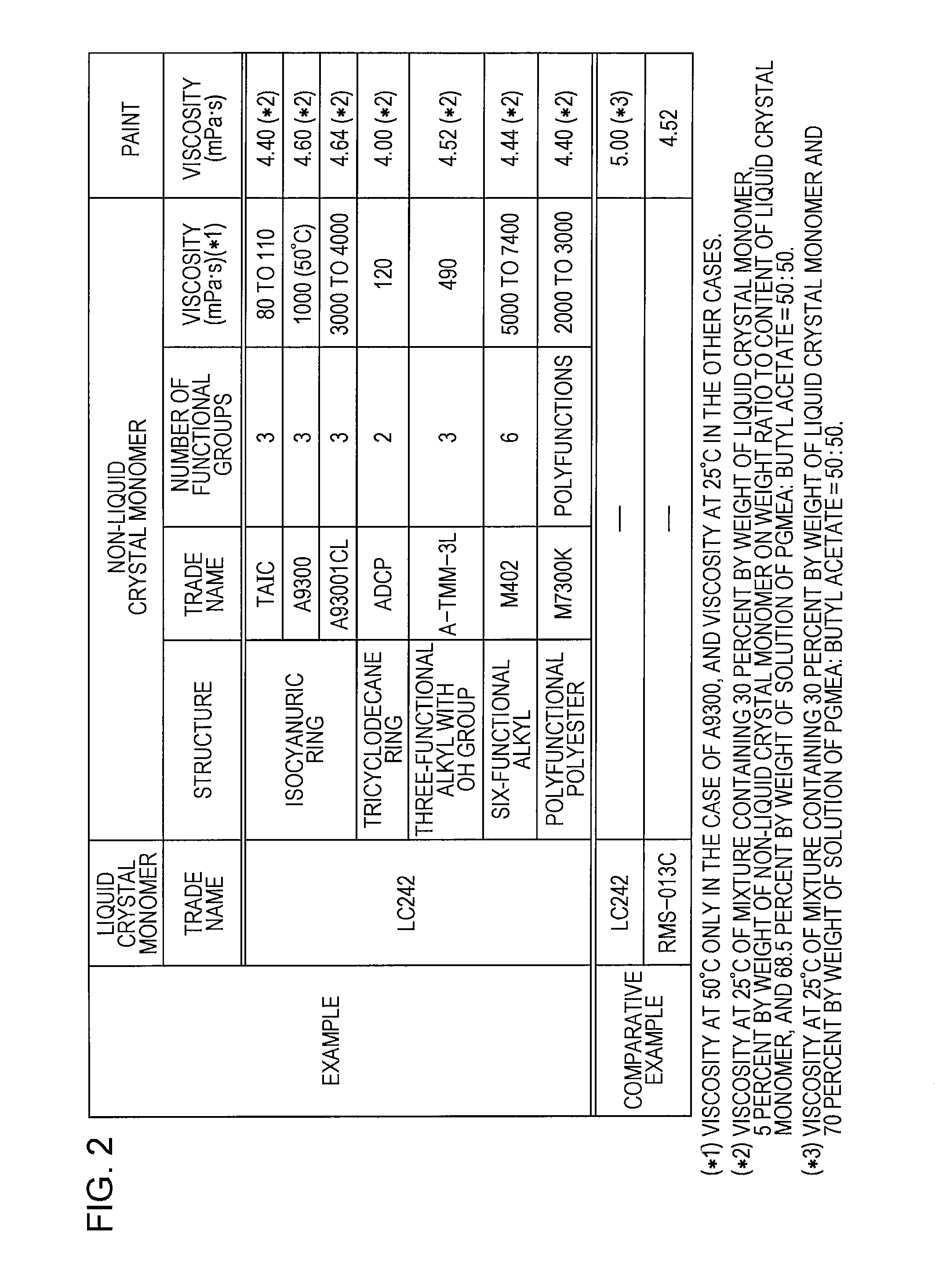
[0055]Columns of an example of FIG. 2 show materials used as the liquid crystal monomer 10 and the non-liquid crystal monomer 20 by way of example. Columns of a comparative example of FIG. 2 show liquid crystal paints which are now commercially available. Although the columns of the example of FIG. 2 show the materials which can be used as the liquid crystal monomer 10 and the non-liquid crystal monomer 20 by way of example, ...

second embodiment

Modification of Second Embodiment

[0106]In addition, in the retardation element 2 of this embodiment, the alignment film 22 may be formed of a plurality of types of alignment regions in which the extending directions of the fine grooves are different from each other. In this case, the retardation layer 23 is formed of a plurality of types of retardation regions having lagging axes in the directions corresponding to the extending directions of the fine grooves included in the alignment regions.

3. Third Embodiment

[0107]Next, the display device 3 according to a third embodiment of the present disclosure will be described. FIG. 17 is a perspective view showing one example of a cross-sectional structure of the display device 3. The display device 3 is a polarized glass type display device which displays a stereoscopic image to a viewer (not shown) wearing a pair of polarized glasses 6, which will be described later, in front of the eyeballs of the viewer. This display device 3 is formed b...

third embodiment

Modification of Third Embodiment

[0142]Although the two types of retardation regions (right-eye region 23A and left-eye region 23B) in which the directions of the lagging axes are different from each other are provided in the retardation element 2 according to the above third embodiment, at least three types of retardation regions in which the directions of the lagging axes are different from each other may also be provided.

[0143]In addition, although the case in which the retardation regions (right-eye regions 23A and left-eye regions 23B) of the retardation element 2 extend horizontally is described in the third embodiment by way of example, the retardation regions may also extend in another direction.

[0144]In addition, although the case in which the retardation element 2 is applied to the display device 3 is described in the third embodiment and the modification thereof by way of example, of course, the retardation element 2 may also be applied to other devices.

[0145]Furthermore, ...


PUM

PropertyMeasurementUnit
temperatureaaaaaaaaaa
areaaaaaaaaaaa
temperatureaaaaaaaaaa

Abstract

A retardation element includes an alignment film and a retardation layer in contact with a surface of the alignment film, and the retardation layer is formed by applying a paint containing a liquid crystal monomer and a non-liquid crystal monomer on the surface of the alignment film and then polymerizing the paint while the liquid crystal monomer is placed in an alignment state.

Description

CROSS REFERENCE TO RELATED APPLICATION[0001]The present application claims priority to Japanese Patent Application No. 2010-285642 filed on Dec. 22, 2010, the disclosure of which is incorporated herein by reference.BACKGROUND[0002]The present disclosure relates to a paint containing a liquid crystal monomer and a retardation element manufactured by using the paint. In addition, the present disclosure relates to a display device including the above retardation element. Furthermore, the present disclosure relates to a method for manufacturing the above retardation element.[0003]As a stereoscopic image display device using a pair of polarized glasses, there has been a device which emits different types of light in polarization state from a left-eye pixel and a right-eye pixel. In the display device as described above, after a viewer wears a pair of polarized glasses, light emitted from a left-eye pixel is allowed to enter only the left eye of the viewer, and light emitted from a right-...

Claims


Application Information

Patent Timeline
Patent Type & Authority Patents(United States)
IPC IPC(8): G02F1/1335C09D4/02C09K19/54C09K19/38G02F1/13363
CPCC09D4/00G02F1/13363C09K2019/2078G02B5/3083C09K2019/0448C09K19/3809C09K19/38C09K19/54G02F1/13G02F1/1335
Inventor OKUNO, MORIAKITSUNODA, YUKARISATO, HARUMIOKUYAMA, KENTAROENOMOTO, MASASHI
Owner DEXERIALS CORP
Why Eureka
Try Eureka