
Compressor flow control

a compressor and flow control technology, applied in the direction of engine controllers, combustion engines, machines/engines, etc., can solve the problems of compressor degradation, insufficient boost to meet current torque requests, performance problems, etc., and achieve the effect of expanding the operating region of an engin

Inactive Publication Date: 2014-06-03
FORD GLOBAL TECH LLC
View PDF6 Cites 10 Cited by
  • Summary
  • Abstract
  • Description
  • Claims
  • Application Information

AI Technical Summary

Benefits of technology

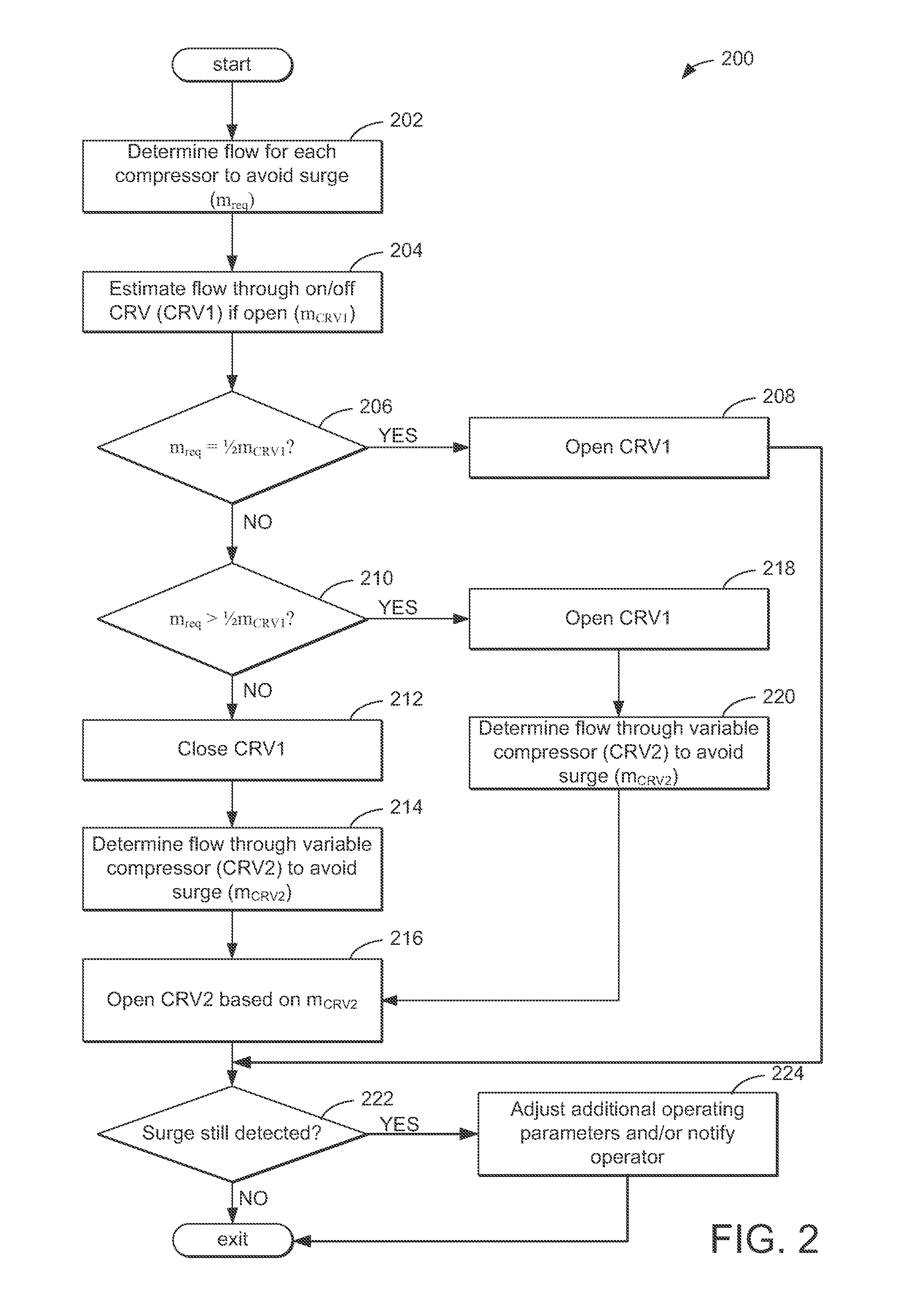
[0005]In this way, the second, variably adjustable compressor recirculation valve may be operated to provide an adjustable amount of intake flow that recirculates through the compressor. The first compressor recirculation valve, which is a traditional on / off compressor recirculation valve, may be operated to alleviate compressor surge, for example, under high load conditions. Together, compressor surge may be mitigated by concerted control of both valves, leading to reduced noise disturbances while providing acceptable boost in transient conditions. Additionally, in engine systems that include a single turbocharger, the two compressor recirculation valves may be arranged in parallel to recirculation the one compressor, and controlled to mitigate surge.
[0006]The present disclosure may offer several advantages. For example, an engine that includes both the first and second compressor recirculation valves as described may be extensively downsized to improve engine efficiency and fuel economy, as the variably adjustable valve allows for engine operation close to the surge boundary while avoiding surge and providing sufficient boost. Boost under transient conditions may also be improved, as the variably controlled compressor recirculation valve allows for proper boost for adequate torque response following, for example, a sudden drop in engine load during an operator tip-out event.

Problems solved by technology

Under certain conditions, the flow rate and pressure ratio across the compressor can fluctuate to levels that may result in noise disturbances, and in more severe cases, performance issues and compressor degradation.
However, at some operating conditions, opening the CRV to mitigate noise issues may result in insufficient boost to meet current torque requests.
Particularly, this may result in poor response in transient conditions, such as following a partial throttle tip-out.

Method used


Image

  • Compressor flow control
  • Compressor flow control
  • Compressor flow control

Examples


Embodiment Construction

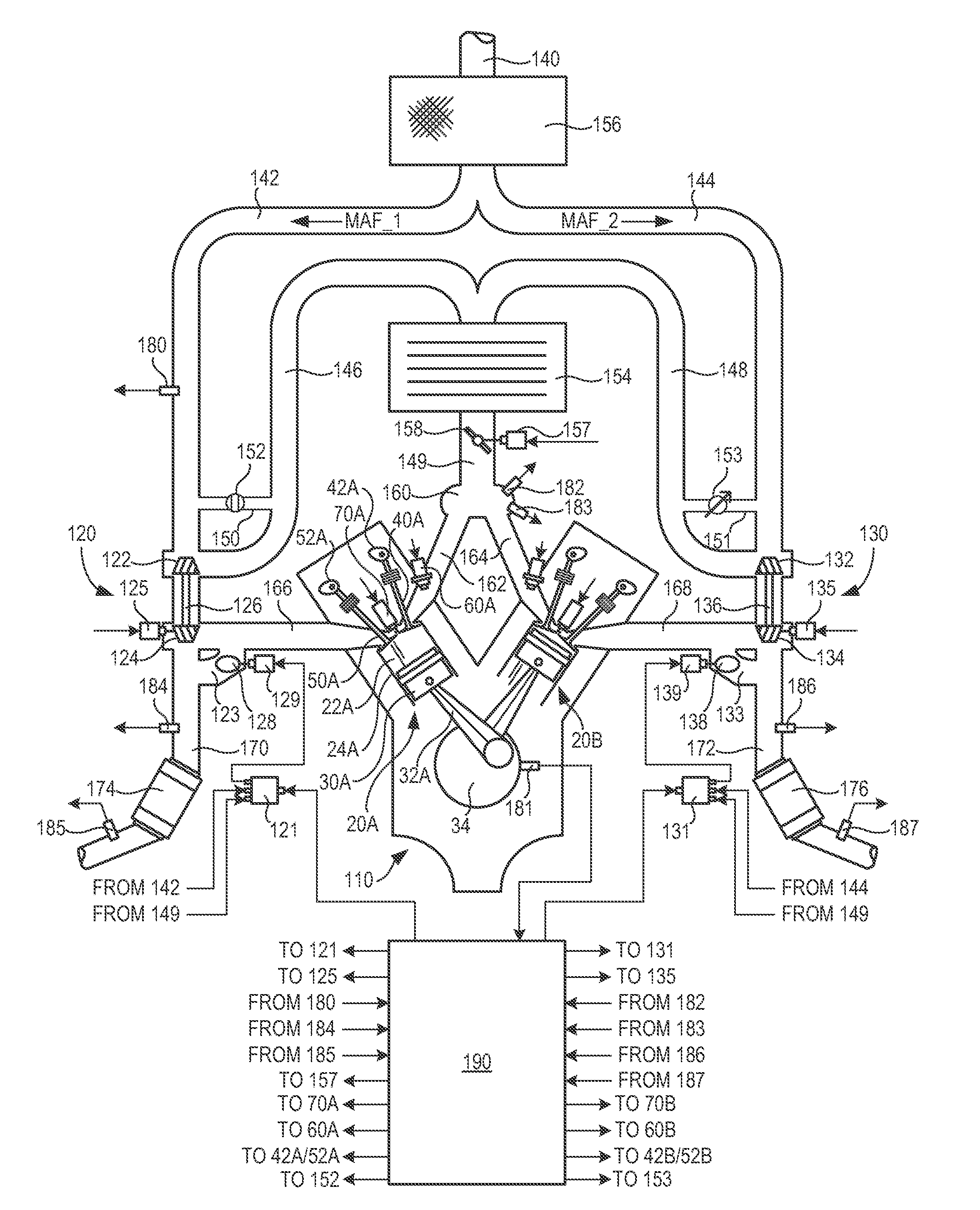
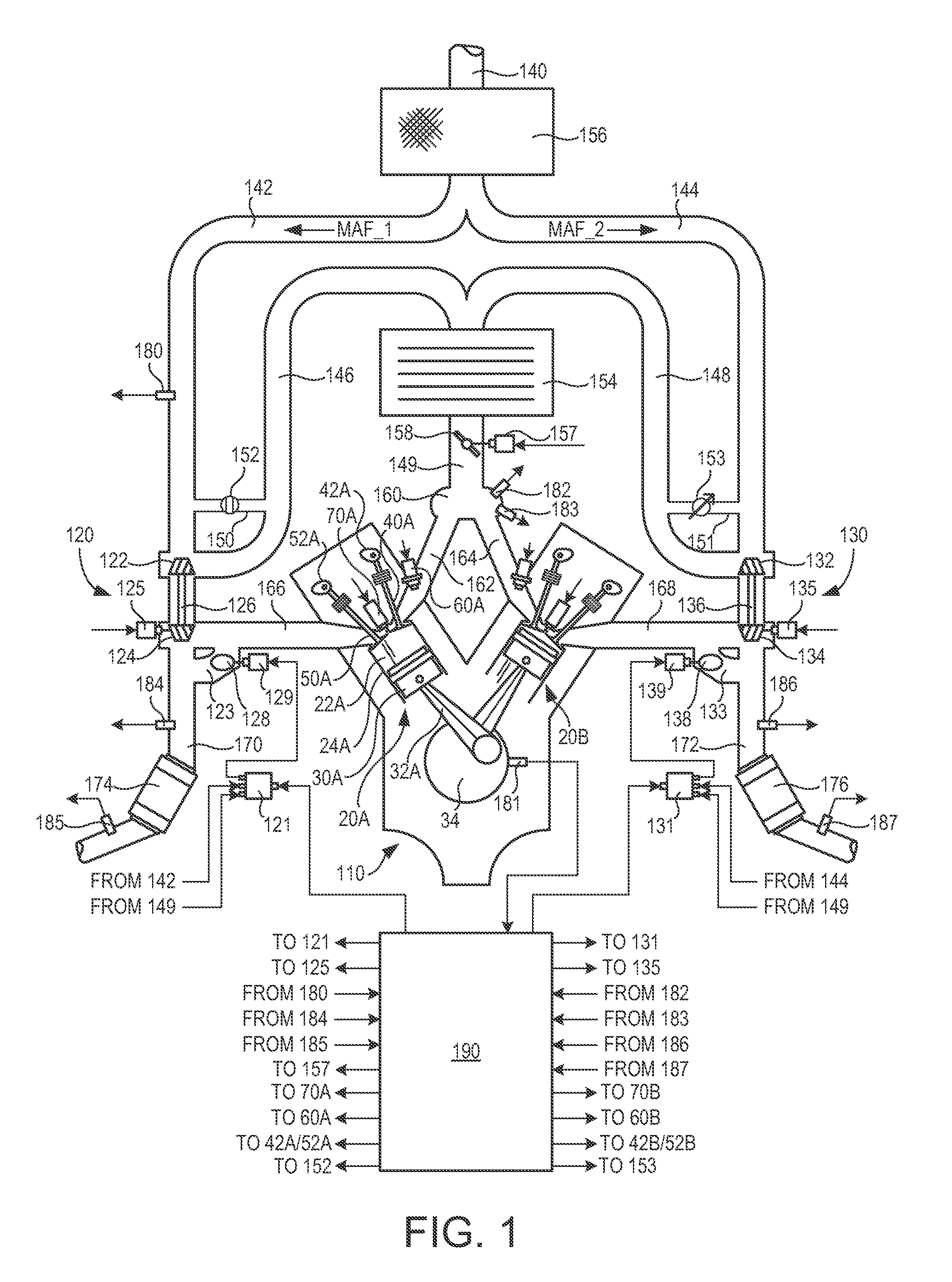
[0012]Turbo charging of an engine allows for smaller displacement engines with similar power output of larger engines. Extensively downsized engines often operate very near a surge boundary, where flow conditions across a compressor may push the compressor into surge, which can degrade the compressor. To avoid surge, a compressor recirculation valve may be opened to reduce pressure downstream of the compressor and increase flow through the compressor. However, particularly under transient conditions, the large flow amounts through the recirculation valve can lead to inadequate and / or delayed boost for the current power demands. To provide optimal flow amount through the recirculation valve, a traditional on / off recirculation valve may be replaced with a variably adjustable recirculation valve. The restriction level of the recirculation valve may be controlled based on pressure and flow across the compressor to avoid surge while maintaining adequate boost. FIG. 1 depicts an engine in...


PUM


Abstract

An engine system is provided. The system comprises an engine, first and second compressors supplying air to the engine, a first compressor recirculation valve adjustable to two restriction levels, and a second compressor recirculation valve adjustable to three or more restriction levels. In this way, the first and second compressor recirculation valves may be controlled to avoid compressor surge while providing a sufficient amount of boost to meet power demands.

Description

FIELD[0001]The present disclosure relates to compressor flow in a turbocharged engine.BACKGROUND AND SUMMARY[0002]Turbo charging an engine allows the engine to provide power similar to that of a larger displacement engine. Thus, turbo charging can extend the operating region of an engine. Turbochargers function by compressing intake air in a compressor via a turbine operated by exhaust gas flow. Under certain conditions, the flow rate and pressure ratio across the compressor can fluctuate to levels that may result in noise disturbances, and in more severe cases, performance issues and compressor degradation.[0003]Such compressor surge may be mitigated by one or more compressor recirculation valves (CRV) located in the intake. The CRVs may recirculate compressed air from the compressor outlet to the compressor inlet. However, at some operating conditions, opening the CRV to mitigate noise issues may result in insufficient boost to meet current torque requests. Particularly, this may ...

Claims


Application Information

Patent Timeline
Patent Type & Authority Patents(United States)
IPC IPC(8): F02B37/12
CPCF02B37/001F02B37/127F02D23/00F02B37/007Y02T10/144F02B37/18F02B2037/125F02B2037/162F02B37/16F02B37/162Y02T10/12
Inventor BJORGE, DEBORAH M.BUCKLAND, JULIA HELEN
Owner FORD GLOBAL TECH LLC
Learn More