Signal transmission structure

a transmission structure and signal technology, applied in waveguides, waveguide type devices, high frequency circuit adaptations, etc., can solve the problems of increasing the difference in the characteristic impedance from the original design, and the seriousness of the impedance mismatch in the signal line, so as to improve the characteristic impedance mismatch, improve the signal transmission quality, and reduce the resonance induced by the coupling between the first and second reference planes

Active Publication Date: 2006-04-06
VIA TECH INC
View PDF3 Cites 16 Cited by
  • Summary
  • Abstract
  • Description
  • Claims
  • Application Information

AI Technical Summary

Benefits of technology

[0009] Accordingly, an object of the present invention is to provide a signal transmission structure for improving the quality of signal transmission by decreasing power noise interference.
[0010] Another object of the present invention is to provide a signal transmission structure for reducing the characteristic impedance mismatch when the signal line passes through a non-reference area.
[0013] In the signal transmission structure of the present invention, the second reference plane is cut to form a non-reference area opening, i.e. second opening, which is lager than the first opening, such that the resonance induced by the coupling between the first and second reference planes is reduced. Moreover, when the signal passes through the signal line, parasitic capacitance, which is induced by the first reference plane and at least one protrusion portion, is able to improve characteristic impedance mismatch, thus improving signal transmission quality.

Problems solved by technology

Moreover, the difference in the characteristic impedance from the original design is increased such that the impedance mismatch in the signal lines is much more serious.

Method used


Image

  • Signal transmission structure
  • Signal transmission structure
  • Signal transmission structure

Examples


first embodiment

[First Embodiment]

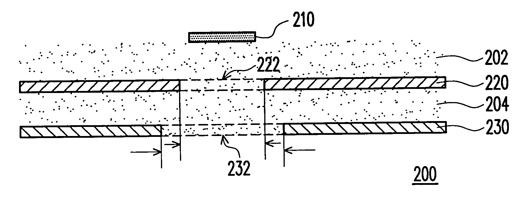
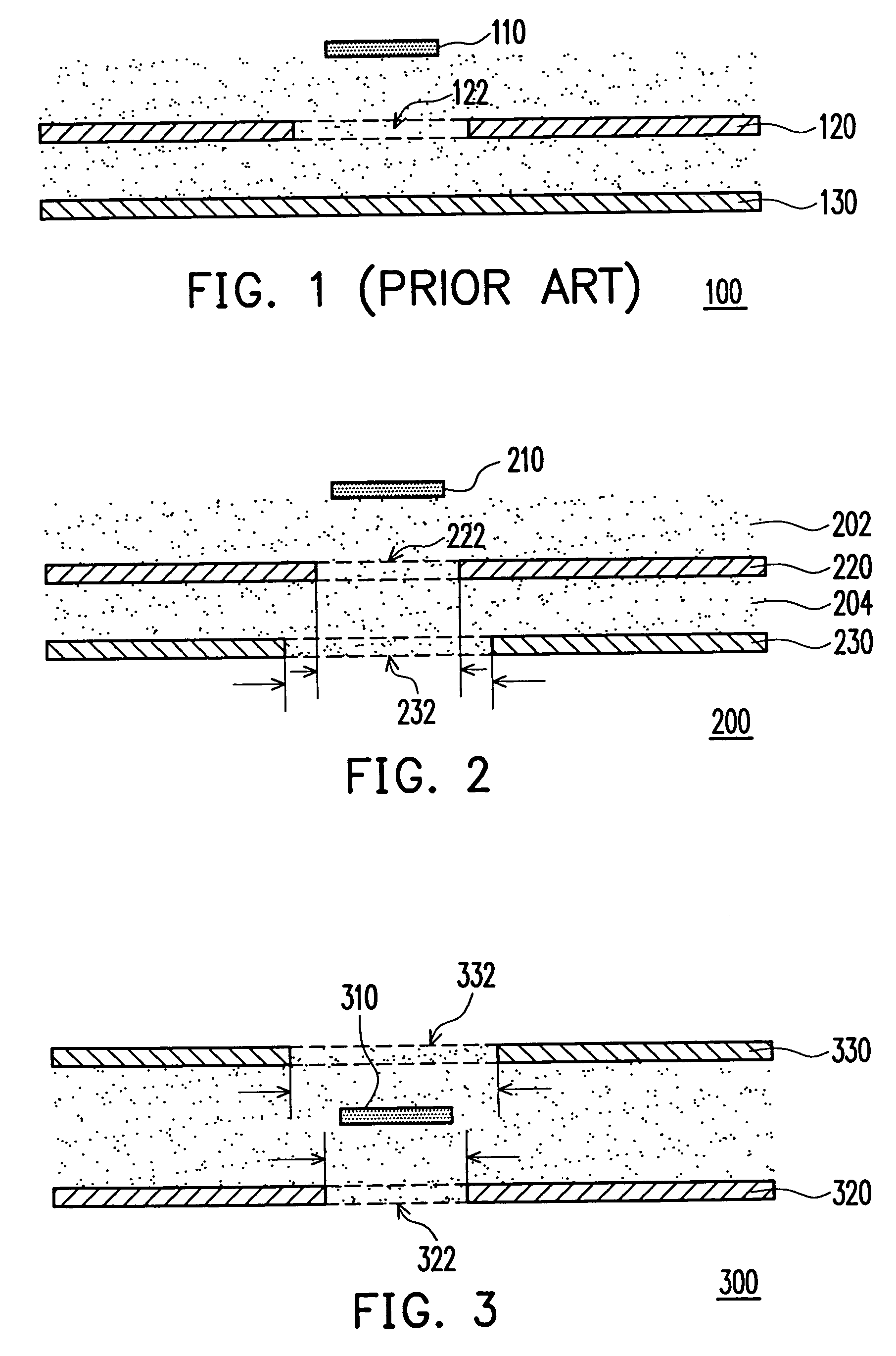
[0020]FIG. 2 shows a cross-sectional view of a signal transmission structure in accordance with a first embodiment of the present invention. The signal transmission structure 200 is adaptive for a circuit board such as a printed circuit board or a packaging substrate. The signal transmission structure 200 comprises a signal line 210, a first reference plane 220 and a second reference plane 230. The signal line 210, for example, is a signal line with uniform width. The first reference plane 220 is positioned at one side of the signal line 210. The signal line 210 can be overlapped the first reference plane 220 with dielectric layers 202 in between, and the first reference plane 220 can be overlapped the second reference 230 with dielectric layer 204 in between. Moreover, the first reference plane 220, for example, is a power plane or a ground plane, and has a non-reference area formed thereon due to drilling or cutting, such as a non-reference area opening 222 (i.e....

second embodiment

[Second Embodiment]

[0023]FIG. 3 shows a cross-sectional view of a signal transmission structure in accordance with a second embodiment of the present invention. The signal transmission structure 300 comprises a signal line 310, a first reference plane 320 and a second reference plane 330. Different from the first embodiment, the first reference plane 320 and the second reference plane 330 are respectively positioned above and below the signal line 310. The signal line 310, for example, is with uniform width. The first reference plane 320 and the second reference plane 330 are, for example, a power plane and a ground plane. Due to drilling or cutting, a portion of the first reference plane 320 and the second reference plane 330 form a non-reference area. For example, a first opening 322 and a second opening 332 of the non-reference areas are respectively formed on the first reference plane 320 and the second reference plane 330, wherein the second opening 332 is in a position corresp...

third embodiment

[Third Embodiment]

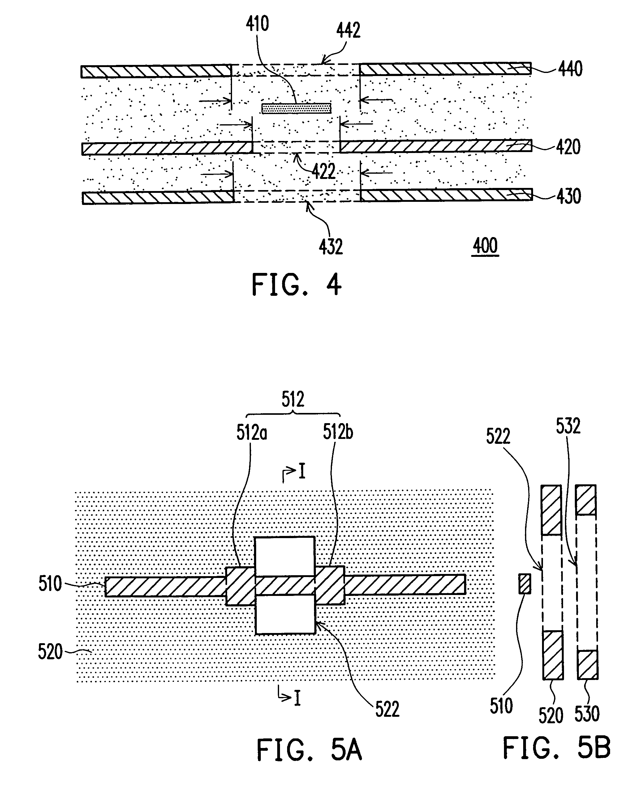
[0025]FIG. 4 shows a cross-sectional view of a signal transmission structure in accordance with the third embodiment of the present invention. The signal transmission structure 400 comprises, for example, a signal line 410, a first reference plane 420, a second reference plane 430 and a third reference plane 440. Compared with the previous embodiments, the first reference plane 420 and the second reference plane 430 are positioned at the same side of the signal line 410, for example, and the third reference plane 440 is positioned at an opposite side of the signal line 410. The signal line 410 is, for example, with uniform width. The first reference plane 420, the second reference plane 430 and the third reference plane 440 are, for example, a power plane and a ground plane. Due to drilling or cutting, a portion of the first reference plane 420, the second reference plane 430 and the third reference plane 440 form a plurality of non-reference areas which are, for e...


PUM


Abstract

A signal transmission structure including a signal line, a first reference plane with a first opening, and a second reference plane with a second opening is provided. The first reference plane is disposed beside the signal line, and a portion of the signal line passes through a position of the first opening. In addition, the second reference plane is disposed beside the first reference plane, and the second opening is in a position corresponding to the position of the first opening, while the outline of the second opening projected onto the first reference plane does not overlap with the position of the first opening. Therefore, at high frequency-transmission, the above structure can reduce the insertion loss resulted from impedance mismatch as the signal passes through the opening, and reduce the resonance induced by the coupling between two reference planes to enhance the quality of signal transmission.

Description

CROSS-REFERENCE TO RELATED APPLICATION [0001] This application claims the priority benefit of Taiwan application serial no. 93129967, filed on Oct. 4, 2004. BACKGROUND OF THE INVENTION [0002] 1. Field of the Invention [0003] This invention generally relates to a signal transmission structure, and more particularly to a signal transmission structure for minimizing the power noise induced when signals pass through non-perfection reference plane. [0004] 2. Description of Related Art [0005] The signal line for connecting two devices or two terminals in a large-scale printed circuit board or a packaging substrate has to maintain a uniform line width in order to keep a constant characteristic impedance when an electronic signal is transmitted in the signal line. A good impedance matching design between two terminals is required to reduce the reflection due to the impedance mismatch especially when the signal is transmitted in a high speed and a high frequency environment. That is, the ins...

Claims


Application Information

Patent Timeline
Patent Type & Authority Applications(United States)
IPC IPC(8): H01P3/08
CPCH01P3/081H01P3/085H01P3/088H05K1/0253H05K2201/09309H05K2201/0969H05K2201/09727
Inventor HSU, JIMMY
Owner VIA TECH INC
Why Eureka
Try Eureka