Pivoting twin arm support for free weights

a technology of free weights and supports, applied in the field of free weights supports, can solve the problems of unsuitable starting positions for one user during training or exercise sessions, and the use of free weight assemblies during training or exercise sessions, and achieve the effects of improving safety, facilitating the placement of free weights, and facilitating the use of free weights

Inactive Publication Date: 2014-06-03
YORK RYAN JOHN +1
View PDF9 Cites 17 Cited by
  • Summary
  • Abstract
  • Description
  • Claims
  • Application Information

AI Technical Summary

Benefits of technology

[0009]The invention is a support designed to support light and heavy weight dumbbells and barbells, while improving safety when compared to conventional lifting methods. The invention supports free weight movements from inclined and declined weight lifter's benches, as well as flat bench press exercises and shoulder press exercises. The invention relies primarily on two support arms that are adjustable in an angular fashion. The angular adjustments allow the user to easily position free weights at different elevations, giving the device greater versatility than prior configurations. The invention incorporates a pair of pivoting arms, at one end of which are disposed holders for free weights. The pivoting arms are easily adjusted to establish angle settings for positioning free weights for the appropriate position to start a particular weight lifting exercise. The invention utilizes counter weights to allow smooth and easy rotation of the arms. By providing the invention with wheels or casters, the device is mobile and can be moved between locations simply by lifting one end of the device utilizing the primary arms and rolling on casters. The invention has been optimized in width and height to be versatile in the weight training environment.

Problems solved by technology

Whether barbells or dumbbells, the free weight assemblies used during a training or exercise session are, by design, heavy.
Further, because of the differences between the physical dimensions of individual participants, a starting position for one user may be unsuitable for another.

Method used


Image

  • Pivoting twin arm support for free weights
  • Pivoting twin arm support for free weights
  • Pivoting twin arm support for free weights

Examples


Embodiment Construction

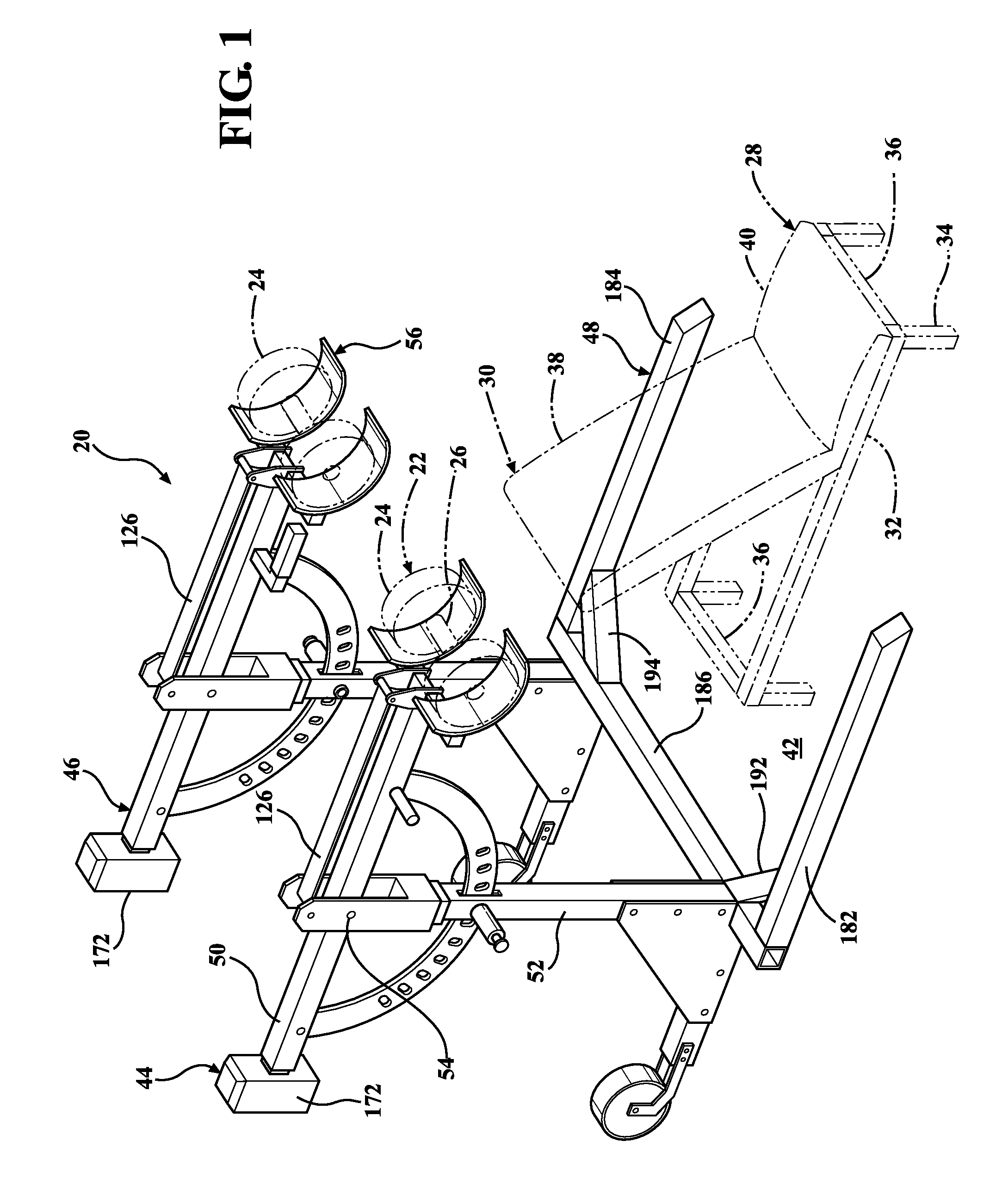
[0025]With reference to FIGS. 1-14, a free weight support apparatus 20 may be used to support a dumbbell 22 (see FIG. 1) generally consisting of one or more weight elements 24 interconnected by a cross bar 26. The free weight support apparatus 20 may be used in conjunction with a weight lifter's bench 28, or may be used by a participant in weight lifting activities that is standing or otherwise positioned in relation to a free weight to be manipulated in a weight lifting exercise. These exercises may be conducted on or near the weight lifter's bench 28.

[0026]The weight lifting bench 28 may include a support 30 for the back, hips and legs. The support 30 may be attached to a frame 32 having one or more support legs 34 and one or more cross-members 36. The support 30 may include two or more individually adjustable sections. For example, a back support 38 may provide support for the user's back and upper hip region, and a seat support 40 may support the lower hip region and legs. The b...


PUM


Abstract

An apparatus for supporting a weight lifting dumbbell includes a riser and a cradle support arm pivotally attached to the riser at a first pivot connection. The cradle support arm may be selectively rotated around the first pivot connection between a raised position and a lowered position. The apparatus may also include a cradle for supporting a free weight. The cradle is pivotally connected to the cradle support arm at a second pivot connection. Moving the cradle support arm between the raised and lowered positions causes the second pivot connection to rotate around the first pivot connection in response to the cradle support arm being rotated around the first pivot connection. The apparatus may further include a cradle actuating link pivotally connected to the riser and the cradle. The cradle actuating link operates to cause the cradle to rotate counter to the rotation of the cradle support arm.

Description

RELATED APPLICATIONS[0001]This application claims benefit of U.S. Provisional Application No. 61 / 722,443 filed on Nov. 5, 2012, which is incorporated by reference herein in its entirety.FIELD OF THE INVENTION[0002]The present invention pertains to exercise equipment, and more particularly, to supports for free weights used in association with weight lifting and weight lifting benches.DESCRIPTION OF THE RELATED ART[0003]Participants in the sport of weight lifting frequently utilize a broad range of training equipment, including a variety of free weights. Free weights are traditional barbells and dumbbells incorporating a cross-member and one or more disc-like weights removably attached too opposing ends of the cross-member. Typically, assemblies of free weights manipulated by both arms of the user are described as barbells, while smaller assemblies of cross bars and free weights manipulated by one arm are referred to as dumbbells.[0004]Regardless of which type of free weight assembly...

Claims


Application Information

Patent Timeline
Patent Type & Authority Patents(United States)
IPC IPC(8): A63B21/078
CPCA63B21/078A63B2225/093A63B21/0726
Inventor YORK, RYAN JOHNPOLIDAN, JOSEPH THOMAS
Owner YORK RYAN JOHN
Why Eureka
Try Eureka