Eureka AIR delivers breakthrough ideas for toughest innovation challenges, trusted by R&D personnel around the world.

Golf club fitting method, device thereof, and analysis method

a golf club and fitting technology, applied in the field of golf club fitting, can solve the problems of undefined relationship between the hitting result of the golf club and the fitting, and achieve the effect of improving the hitting result and improving the hitting resul

Active Publication Date: 2014-06-10
SUMITOMO RUBBER IND LTD
View PDF13 Cites 5 Cited by
  • Summary
  • Abstract
  • Description
  • Claims
  • Application Information

AI Technical Summary

Benefits of technology

[0037]With the method for analysis according to the present invention, a fit indicator can be identified to improve a hitting result. With the fitting method or device according to the present invention, a golf club which can improve a hitting result can be appropriately fitted by the indicator.

Problems solved by technology

However, in these methods, a relationship between a hitting result of a golf club and fitting remains undefined.

Method used


Image

  • Golf club fitting method, device thereof, and analysis method
  • Golf club fitting method, device thereof, and analysis method
  • Golf club fitting method, device thereof, and analysis method

Examples


example 1

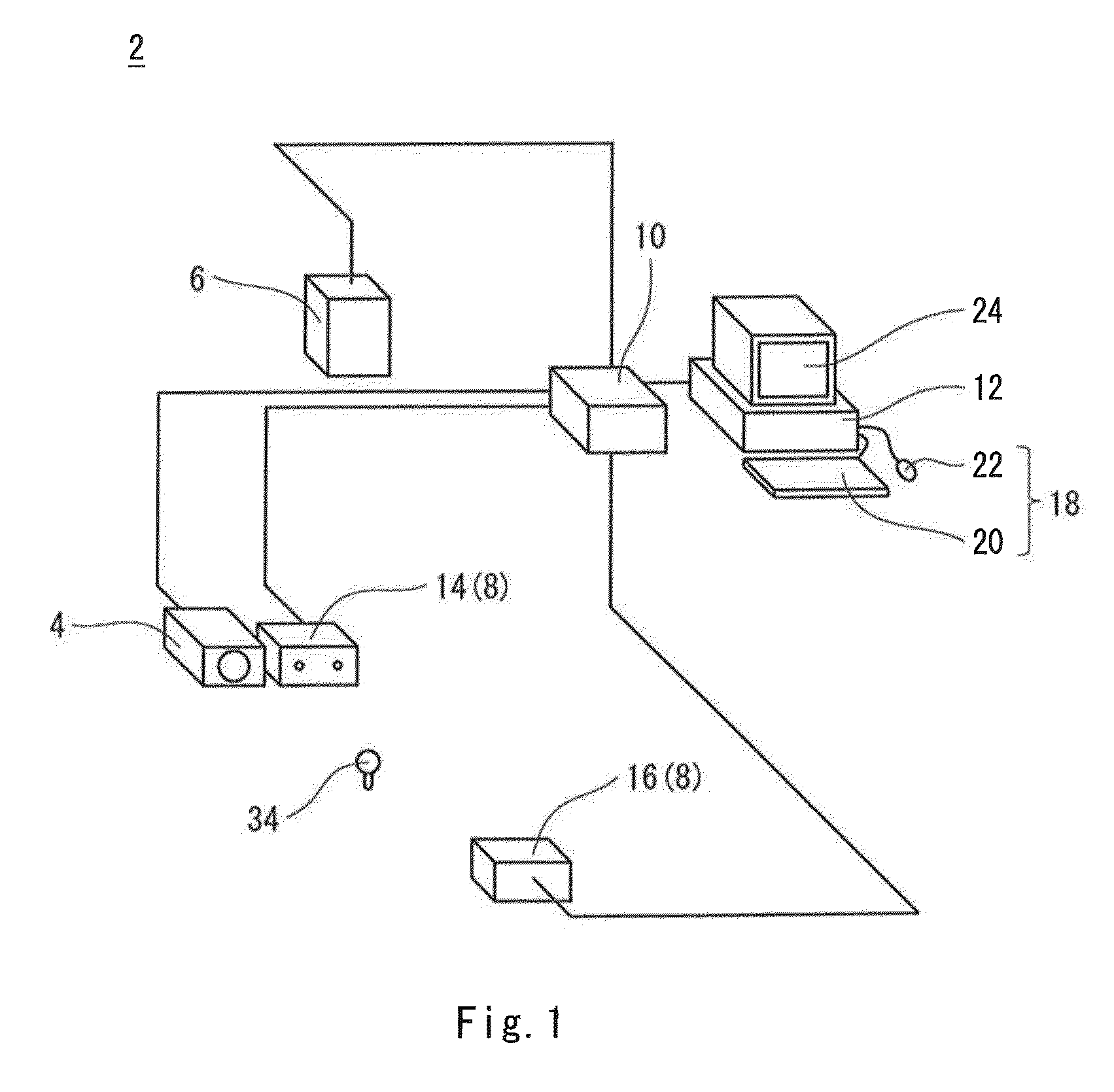
[0191]An indicator was determined by using the analyzer shown in FIG. 7 and with the analysis method shown in FIG. 8. A hitting result is flight distance. A predetermined physical property of a shaft is a flex point. Values of the physical properties is a low flex point, a middle flex point, and a high flex point.

[0192]In general, a shaft an end side of which tends to bend is referred to as a low flex point. In addition, in generally, a shaft a back end side of which tends to bend is referred to as a high flex point. Designations of the low flex point and the high flex point are known on the market as an indicator which shows a characteristic of a shaft. However, a standard of the low flex point and the high flex point is not necessarily uniform among those in the art. The actual condition is that a plurality of standards of a flex point exists.

[0193]In the embodiment, a flex point rate C1 determined with the following expression 3 is determined. A flex point whose flex point rate C...

example 2

[0210]For the face angle, the right / left initial-launch angle, the side spin rate, the swing plane angle, the shoulder twist angle, and the swing direction travel distance, an accuracy rate of (STEP 10) of FIG. 9 was further calculated. Table 1 shows results.

[0211]

TABLE 1Evaluation resultIndicatorsAccuracy Rate (%)Face angle72Shoulder twist angle63Right / left Initial-launch angle59Swing plane angle53Swing direction travel distance53Side spin53

[0212]Of the indicators in Table 1, the indicator with the highest accuracy rate was the face angle. The face angle is determined as the indicator.

[0213]In the Examples 1 and 2, the golf club is fitted from the three types of golf clubs with different shaft flex points. At any indicator, the accuracy rate of 50% or higher is obtained. In addition, in the fitting with the shoulder twist angle as the indicator, the accuracy rate of 60% or higher is obtained. In the fitting with the face angle as the indicator, the accuracy rate of 70% or higher is...


PUM


Abstract

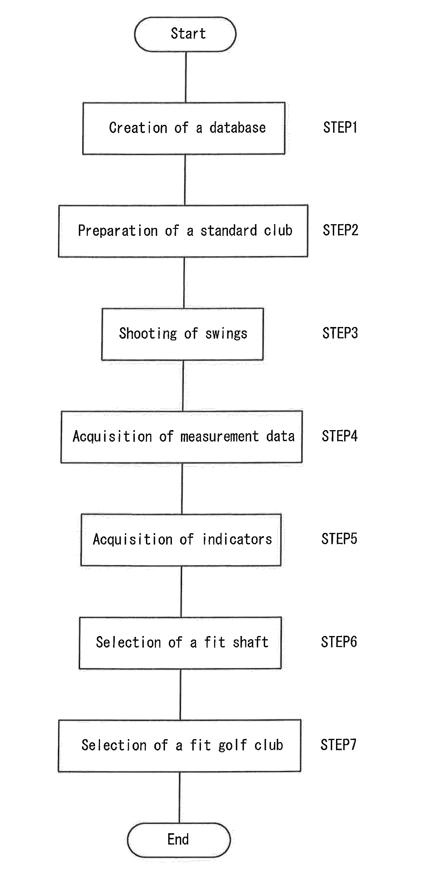
The analysis method includes steps of acquiring measurement data obtained from swings and values of hitting results (flight distance or the like) (STEP 3); calculating a characteristic value (face angle or the like) from the measurement data (STEP 4); and determining an indicator for selecting a shaft of a golf club from the characteristic value and the values of hitting results (STEP 5). In the step of determining an indicator, when a hitting result of a golf club is an objective variable, and the characteristic value is an explanatory variable together with a predetermined shaft physical property (flex point or the like), and has a statistically significant relation with the hitting result, the characteristic value is determined as the indicator. A relational expression of the indicator and the hitting result is calculated for each value of the physical properties.

Description

[0001]This application involves a claim for benefits based on Japanese Patent Application No. 2010-131267 filed on Jun. 8, 2010 and Japanese Patent Application No. 2011-120217 filed on May 30, 2011, which are incorporated herein by reference.BACKGROUND OF THE INVENTION[0002]1. Field of the Invention[0003]The present invention relates to fitting of a golf club.[0004]2. Description of the Related Art[0005]Selection of a golf club which fits a golf player is referred to as fitting. A person who performs fitting of a golf club to a golf player is referred to as a fitter. Physical properties of a shaft of a golf club have a large affect on the fitting.[0006]For example, one of the physical properties of a shaft is flex. The flex represents hardness of a shaft. In general, for the flex, fit hardness is recommended depending on whether head speed is fast or slow. To a golf player whose head speed is relatively slow, a flexible shaft is recommended. To a golf player whose head speed is rela...

Claims


Application Information

Patent Timeline
Patent Type & Authority Patents(United States)
IPC IPC(8): A63B53/00A63B69/36A63B102/32
CPCA63B59/0074A63B69/3623A63B60/42A63B2102/32
Inventor HASEGAWA, HIROSHIONUKI, MASAHIDE
Owner SUMITOMO RUBBER IND LTD
Why Eureka
Eureka Blog
Learn More