
Humanoid electric hand

a technology of electric hands and wrists, applied in the field of humanoid electric hands, can solve the problems of increased weight of electric hands, limited operation of electric hands, unnatural operation of wrist parts, etc., and achieve the effect of light weight and easy maintenan

Inactive Publication Date: 2014-06-10
GIFU UNIVERSITY +1
View PDF18 Cites 39 Cited by
  • Summary
  • Abstract
  • Description
  • Claims
  • Application Information

AI Technical Summary

Benefits of technology

[0009]It is an object of the present invention to provide a humanoid electric hand that is light-weighted and easily maintained.
[0011]According to this configuration, when the finger motor rotates, the rotation is decelerated by the worm deceleration mechanism and then allows the output gear to move rotationally. In response to the rotational movement of the output gear, the metacarpophalangeal joint of the finger bends or extends. When the metacarpophalangeal joint bends or extends, the interphalangeal joint that is linked to the metacarpophalangeal joint via the link mechanism bends or extends together with the movement of the metacarpophalangeal joint. Thereby, it is possible to bend or extend the finger by the simple configuration including only the single motor, the worm deceleration mechanism, and the link mechanism. This makes it possible to reduce the weight of the humanoid electric hand. Further, as the finger is bent or extended without using wires, the frequency of replacing parts is reduced and maintenance is facilitated.
[0013]Further, according to this configuration, the driving link that is formed by the elastic members and the two parts linked via the elastic members is employed for the link mechanism to link the metacarpophalangeal joint and the interphalangeal joint. Thereby, the driving link expands and contracts in response to an external force applied to the fingertip, causing the joint angle of the interphalangeal joint to change elastically. This makes it possible to allow the joint angle of the interphalangeal joint to correspond to the shape of the holding object. Thus, stable holding operation of the object can be performed.
[0016]When holding the object, the force in the direction of changing the joint angle of the interphalangeal joint toward joint extension is applied to the fingertip as a reaction force. According to the above-described configuration, the larger force is required when the joint angle of the interphalangeal joint is changed elastically toward joint extension by the reaction force. This makes it possible to prevent a reduction in the holding force due to extension of the interphalangeal joint while holding the object and to secure the holding force of the object.
[0018]According to this configuration, the holding operation of the object can be performed more easily. Incidentally, the turning operation of the thumb and the bending operations of the rest of the fingers can sandwich and hold the object. At this time, the four fingers, except for the thumb, share and support a pressure of the thumb. This makes it possible to employ the small-sized motor, the maximum output of which is smaller for the finger motor used for the bending or extending operation of each finger. The object can be held appropriately as long as the maximum output of the motor for the turning operation of the thumb can be secured sufficiently.

Problems solved by technology

However, as the wires stretch when used over a long period of time, it is necessary to replace the wires and string the wires again.
This causes an increase in weight of the electric hand.
Further, according to the humanoid electric hands described in Patent Literatures 1 to 3, it is inevitable that operations of wrist portions are performed in an unnatural manner because the wrist portions have no degree of freedom.
As a result of this, operations of the electric hands may be limited, and operation reliability of the electric hands may be decreased.

Method used


Image

  • Humanoid electric hand
  • Humanoid electric hand
  • Humanoid electric hand

Examples


Embodiment Construction

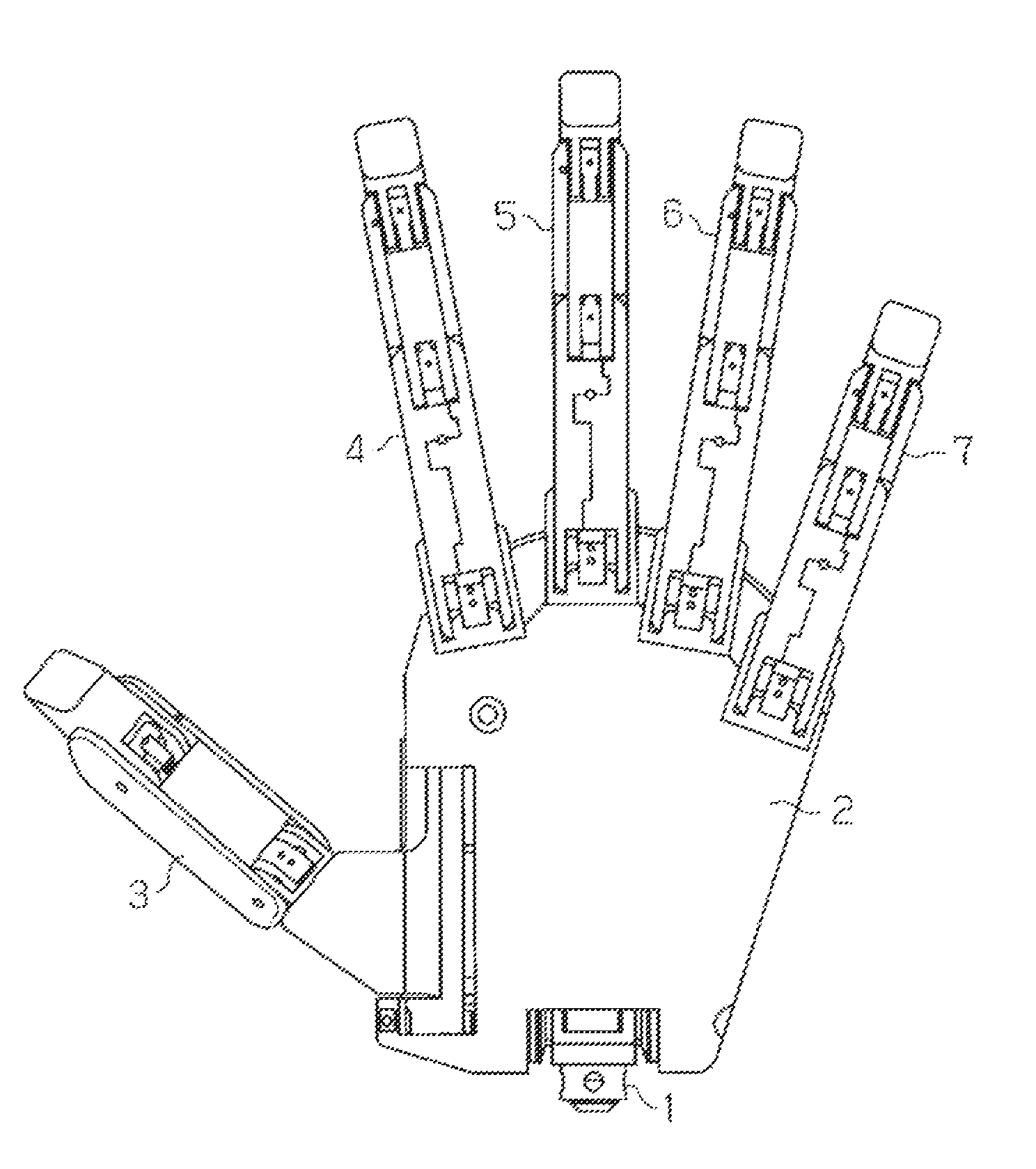
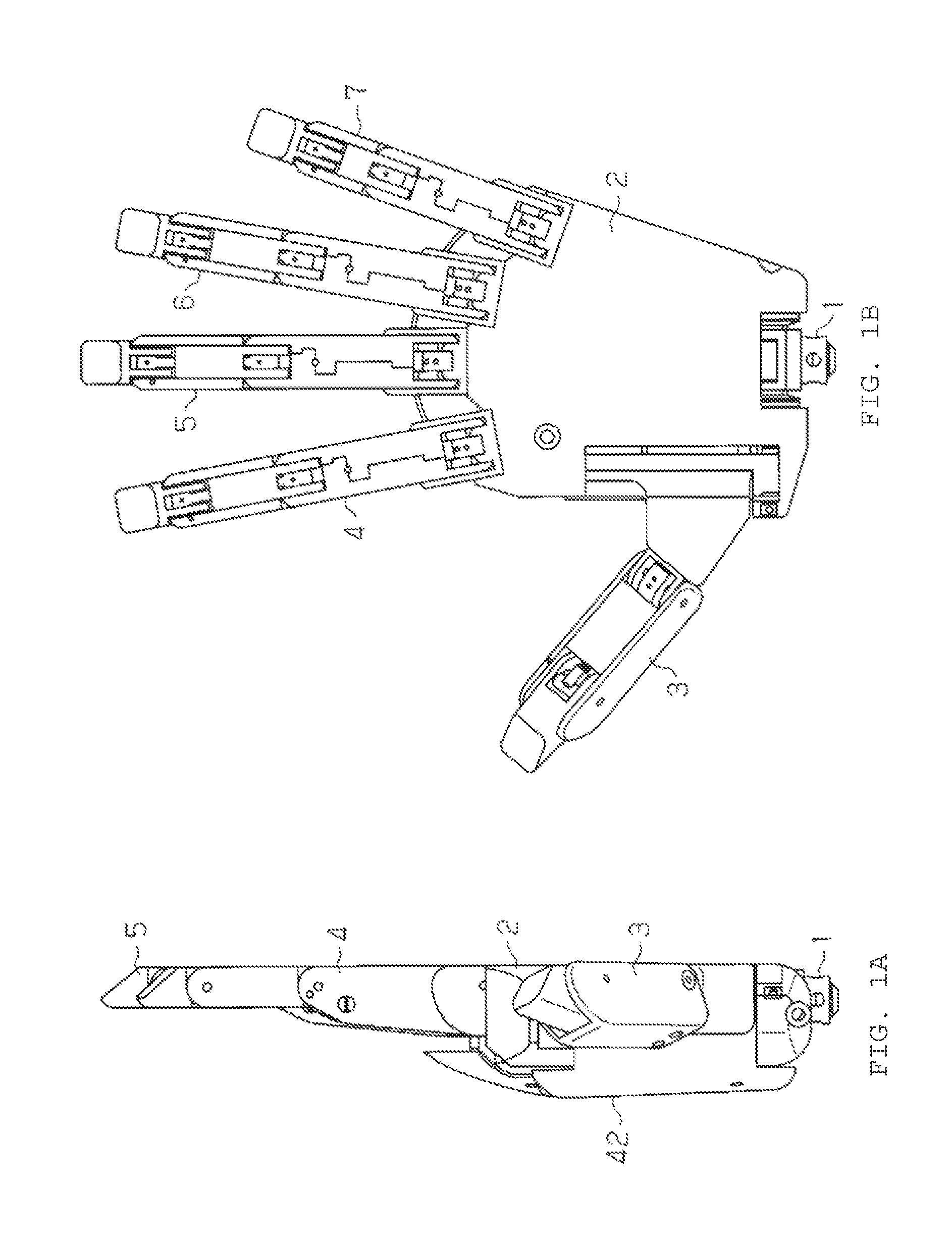
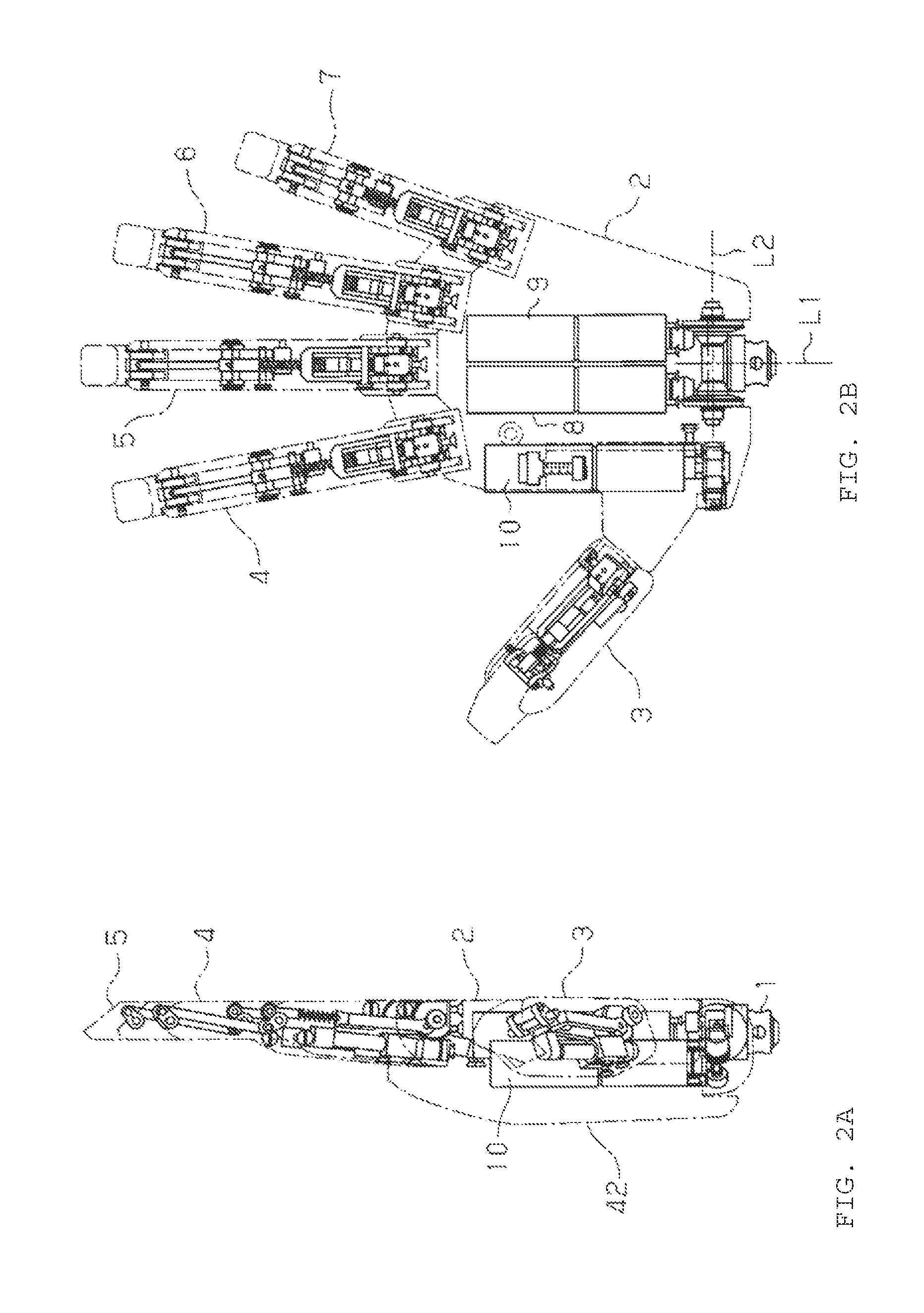
[0037]Hereinafter, a detailed explanation of an embodiment in which a humanoid electric hand of the present invention is embodied will be given with reference to FIG. 1 to FIG. 10. The humanoid electric hand of this embodiment is used as an electric artificial hand.

[0038]As shown in FIG. 1 and FIG. 2, the humanoid electric hand includes a wrist portion 1, a palm portion 2, and five fingers of a thumb 3, an index finger 4, a middle finger 5, a ring finger 6 and a little finger 7. The wrist portion 1 corresponds to a human wrist. The palm portion 2 corresponds to a human palm.

[0039]An artificial skin is attached on the surface of the electric hand. Further, a pressure sensor is arranged between the artificial skin and a frame of each of the fingers. A gel-like high functional material, having a durometer hardness of 12, tensile strength of 9.6 MPa and weight of 64 g, is used as the artificial skin.

(Configuration of Wrist Portion)

[0040]Next, a configuration of the wrist portion 1 will ...


PUM


Abstract

A humanoid electric hand includes a metacarpophalangeal joint and an interphalangeal joint. The interphalangeal joint bends or extends together with a bending or extending operation of the metacarpophalangeal joint, by linking a finger motor for driving a finger to a worm deceleration mechanism, an output gear of which moves rotationally to bend or extend the metacarpophalangeal joint, and by linking the metacarpophalangeal joint to the interphalangeal joint via a link mechanism.

Description

RELATED APPLICATIONS[0001]This application is a national phase application of PCT application PCT / JP2011 / 071716, internationally filed on Sep. 22, 2011, and is filed pursuant to 35 U.S.C. §371, which claims priority to Japanese Application No. 2010-214578, filed Sep. 24, 2010. Both applications are incorporated by reference in their entirety.FIELD OF THE INVENTION[0002]The present invention relates to humanoid electric hands used for electric artificial hands, humanoid robots, and the like.BACKGROUND OF THE INVENTION[0003]Recently, development of humanoid electric hands that are capable of performing holding operations, similarly to human hands, and serve as electric artificial hands or electric hands for humanoid robots has been advanced. According to humanoid electric hands described in Patent Literatures 1 to 3, for example, respective joints of fingers are driven by wires.[0004]As described above, the wires are employed to drive the conventional humanoid electric hands, so that ...

Claims


Application Information

Patent Timeline
Patent Type & Authority Patents(United States)
IPC IPC(8): A61F2/54
CPCA61F2/585A61F2002/6836A61F2002/587B25J15/024B25J15/0009A61F2002/701A61F2/586A61F2/583B25J15/0028A61F2002/5076
Inventor KAWASAKI, HARUHISAMOURI, TETUYAHARA, TATUYASHIMOMURA, HISAYUKI
Owner GIFU UNIVERSITY
Learn More