
Multi-phase clock generation apparatus and method

a multi-phase clock and generator technology, applied in the field of electronic circuits, can solve the problems of narrow bandwidth support, poor noise characteristics, and general low voltage of the circuitry that generates the multi-phase clock

Inactive Publication Date: 2014-06-10
INTEL CORP
View PDF5 Cites 9 Cited by
  • Summary
  • Abstract
  • Description
  • Claims
  • Application Information

AI Technical Summary

Benefits of technology

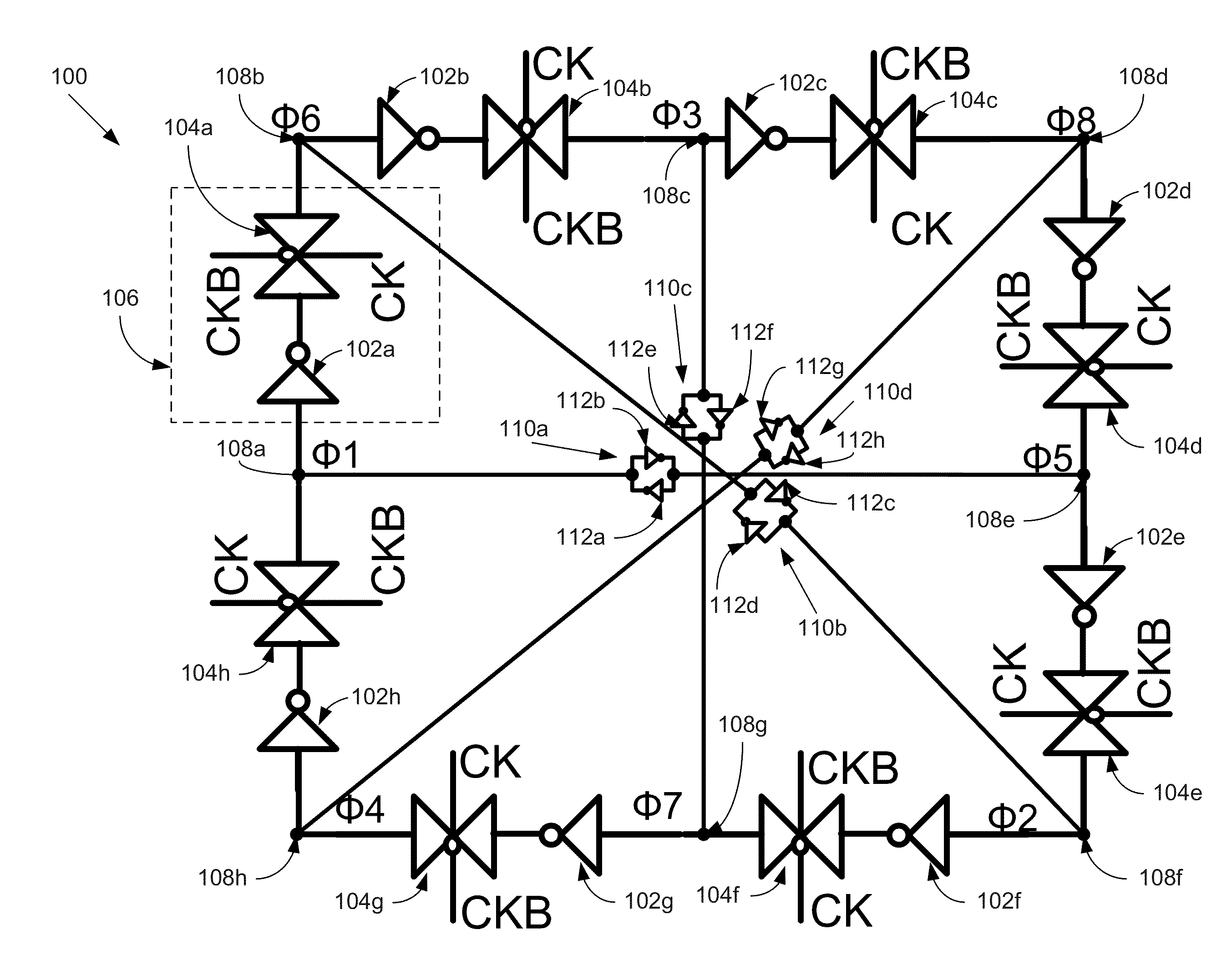
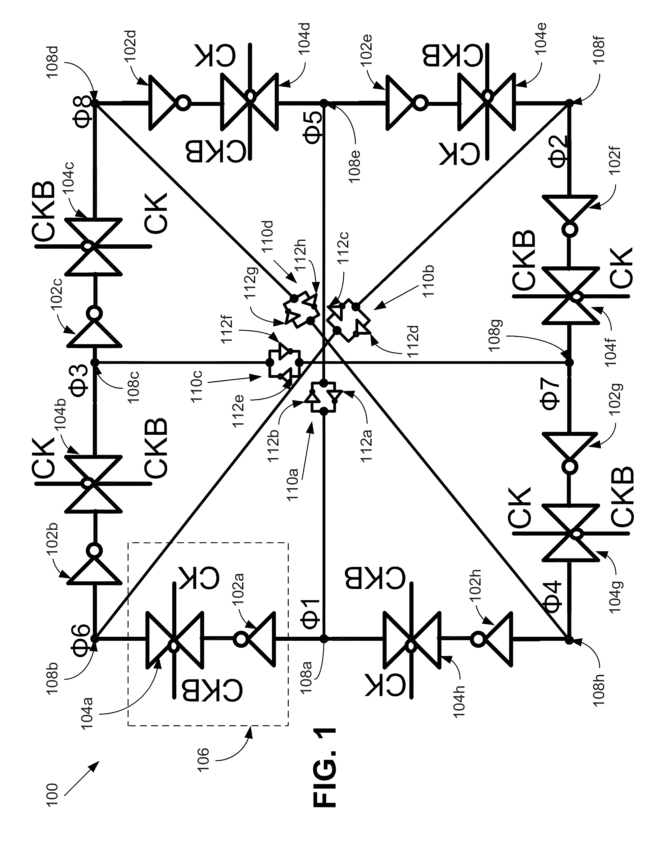
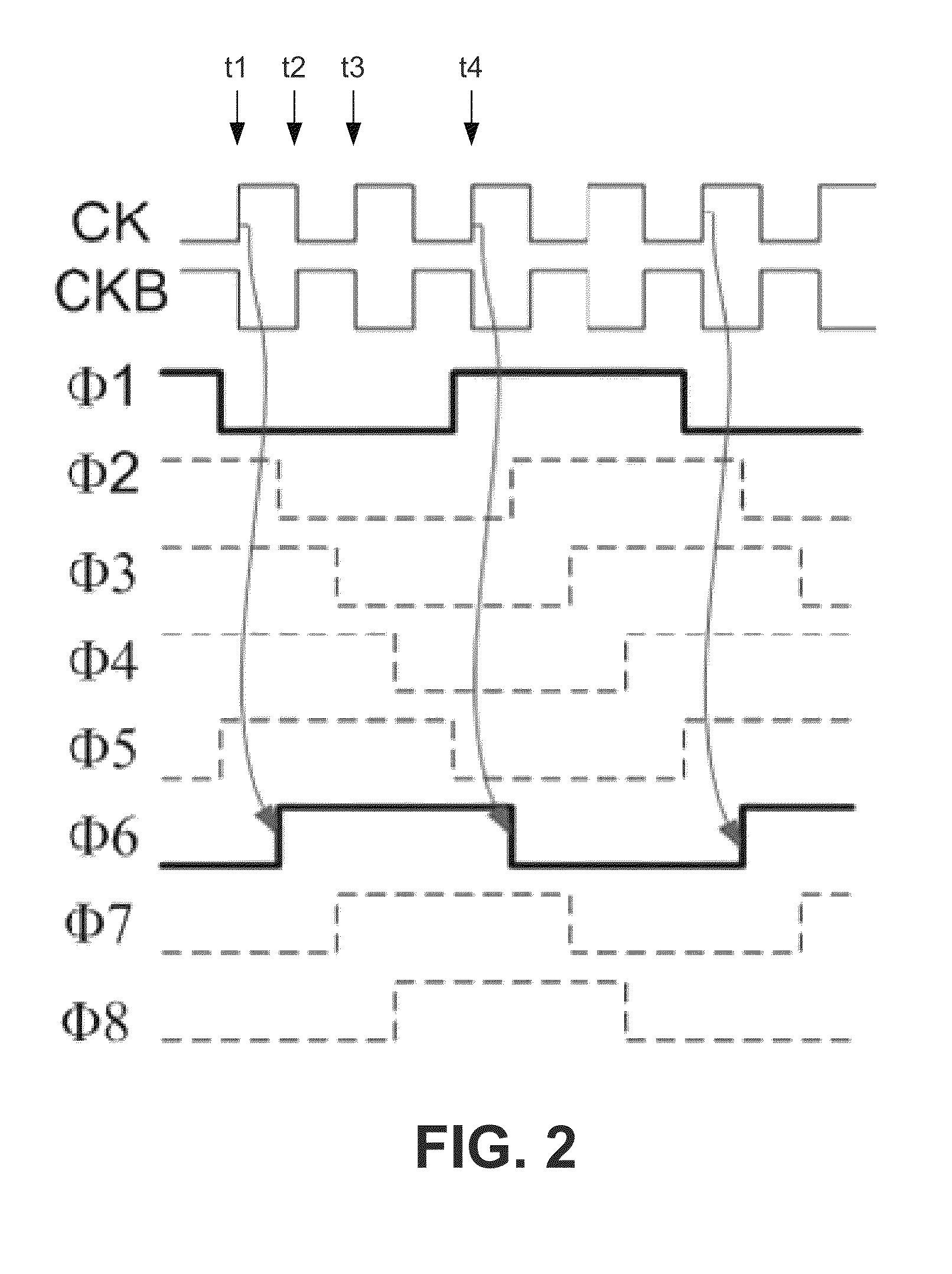
The patent text describes a method and apparatus for generating multi-phase clock signals in electronic circuits. The invention provides a multi-phase clock generator that can operate at low voltage, has narrow bandwidth support, and is more robust against noise. The generator uses a ring oscillator or logic dividers with an external reset or initialization, which does not provide adequate design robustness. The technical effects of the invention include improved performance, reduced power consumption, and better noise immunity. The invention also provides a circuit design for an 8-phase clock generator that produces output clock signals with evenly spaced phases. The generator may be used in computer systems to improve system performance.

Problems solved by technology

However, the circuitry that generates the multi-phase clock generally do not operate at low voltage, have relatively narrow bandwidth support, do not have good noise characteristics, and consume a large amount of power.
Moreover, an external reset or initialization for such circuitry does not provide adequate design robustness.

Method used


Image

  • Multi-phase clock generation apparatus and method
  • Multi-phase clock generation apparatus and method
  • Multi-phase clock generation apparatus and method

Examples


Embodiment Construction

[0011]Embodiments of a method and apparatus for multi-phase clock generation are described herein. In the following description, numerous specific details are given to provide a thorough understanding of embodiments. The embodiments can be practiced without one or more of the specific details, or with other methods, components, materials, etc. In other instances, well-known structures, materials, or operations are not shown or described in detail to avoid obscuring aspects of the embodiments.

[0012]Reference throughout this specification to “one embodiment” or “an embodiment” means that a particular feature, structure, or characteristic described in connection with the embodiment is included in at least one embodiment. Thus, the appearances of the phrases “in one embodiment” or “in an embodiment” in various places throughout this specification are not necessarily all referring to the same embodiment. Furthermore, the particular features, structures, or characteristics may be combined...


PUM


Abstract

A multi-phase clock generator may receive an input clock signal as an input. The clock generator may also receive an inverse of the input clock signal. The clock generator may produce a plurality of output clock signals having different phases. The phases of the output clock signals may be evenly spaced. The output clock signals may have a similar waveform to the input clock signal, with a frequency that is lower than the input clock signal by a division factor.

Description

TECHNICAL FIELD[0001]This disclosure relates generally to electronic circuits. More particularly but not exclusively, the present disclosure relates to apparatuses and methods for multi-phase clock generators in electronic circuits.BACKGROUND INFORMATION[0002]Some electronic components, such as circuit-level devices, integrated-circuit-level devices, board-level devices, and system-level devices, use a multi-phase clock signal. Typically, the multi-phase clock is generated by a ring oscillator, a delay locked loop (DLL), or logic dividers with an external reset or initialization.[0003]However, the circuitry that generates the multi-phase clock generally do not operate at low voltage, have relatively narrow bandwidth support, do not have good noise characteristics, and consume a large amount of power. Moreover, an external reset or initialization for such circuitry does not provide adequate design robustness.BRIEF DESCRIPTION OF THE DRAWINGS[0004]Non-limiting and non-exhaustive embod...

Claims


Application Information

Patent Timeline
Patent Type & Authority Patents(United States)
IPC IPC(8): H03K27/00
CPCG06F1/06H03K5/15013H03L7/0812H03B19/00H03H11/16H03B5/364
Inventor LI, SHENGGAONICHOLSON, ROAN M.
Owner INTEL CORP
Learn More