Auxiliary device for bicycle

a technology for auxiliary devices and bicycles, applied in mechanical devices, transportation and packaging, gearing, etc., can solve problems such as deteriorating cycling endurance and speed, and achieve the effects of reducing burden, enhancing progression, and reducing fatigue in the cyclist's muscles

Inactive Publication Date: 2014-06-17
CHEN SHIA LIN
View PDF27 Cites 2 Cited by
  • Summary
  • Abstract
  • Description
  • Claims
  • Application Information

AI Technical Summary

Benefits of technology

[0006]The primary objective of the present invention is to provide an auxiliary device for a bicycle. The auxiliary device is able to give pressure to a cyclist's back thigh muscles when the cyclist treadles the bicycle's treadles, so as to reduce burden bore by the cyclist's back thigh muscles and shank muscles, and is able to synchronously enhance progression when the cyclist's thighs and shanks exert downward force, thereby reducing fatigue accumulated in the cyclist's muscles and in turn enhancing the cyclist's riding speed and endurance.
[0007]To achieve this and other objectives, the auxiliary device of the present invention is characterized in having a pair of thrusting members and a drive mechanism pivotally coupled between the thrusting members and a bicycle it is assembled to so that the thrusting members normally abut against a cyclist's back thigh muscles. The drive mechanism has two first pivots, a second pivot and a linkage system so as to make the thrusting members thrust the cyclist's back thigh muscles when the cyclist treadles the treadles. Thereby, the auxiliary device is useful to reduce burden bore by the cyclist's front thigh muscles and shank muscles, and can use the kinetic energy generated by the cyclist's back thigh muscles to enhance the cyclist's riding speed and endurance.

Problems solved by technology

During such riding, the cyclist has his / her front thigh muscles (quadriceps) and shank muscles exercised most, and fatigue accumulated in these muscles over time tends to deteriorate the cyclist's riding endurance and speed.

Method used


Image

  • Auxiliary device for bicycle
  • Auxiliary device for bicycle
  • Auxiliary device for bicycle

Examples


first embodiment

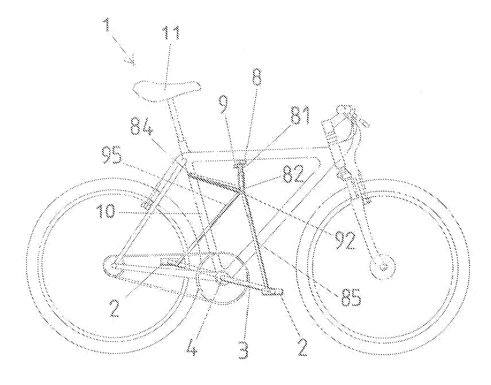
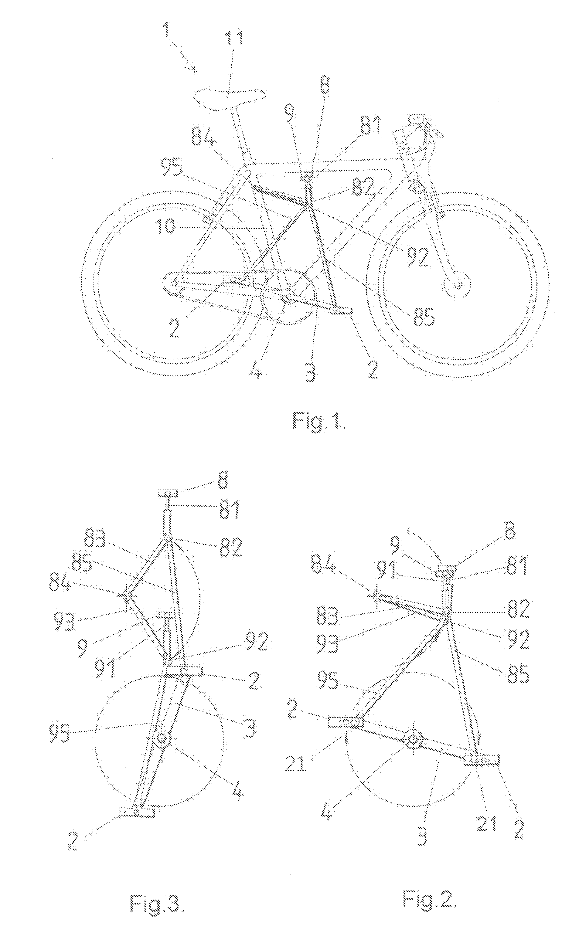
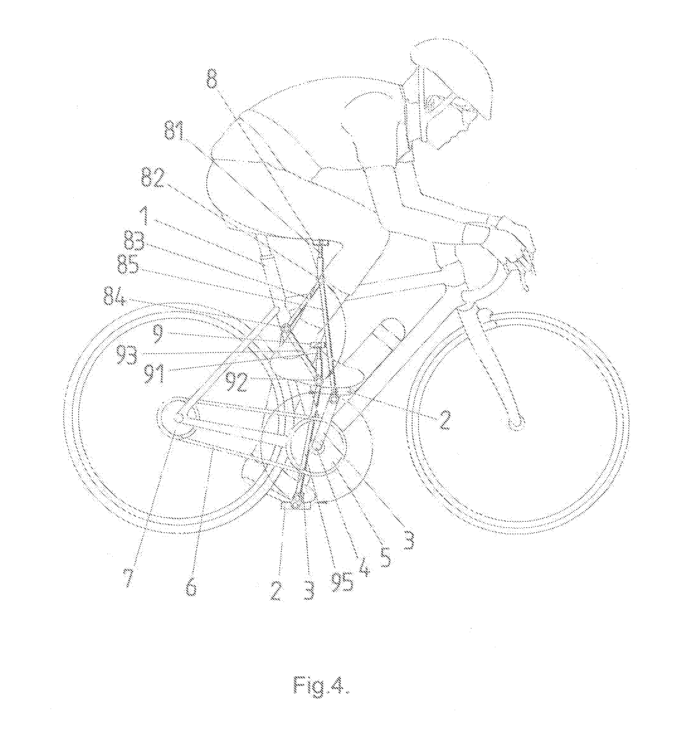
[0022]Please refer to FIGS. 1 through 4 for the auxiliary device of the present invention. As shown in FIG. 1, the disclosed auxiliary device is configured to be assembled to a normal bicycle (or to a tricycle or to other foot-driven devices, such as exercise tools and the like). The normal bicycle typically comprises: a bicycle frame 10, two treadles 2, two cranks 3, a freewheel axle 4, a chain wheel 5, a chain 6, and a rear-wheel axle 7, among others. As shown, the disclosed auxiliary device comprises: a pair of thrusting members 8, 9 and a drive mechanism that is pivotally coupled between the thrusting members and the bicycle 1. The thrusting members 8 and 9 are positioned at two sides of the bicycle frame 10 near a seat 11 of the bicycle 1 in a one-up-one-down manner. The thrusting members 8 and 9 are made of a material comfortable to a cyclist's thighs, and are shaped and sized to fittingly wrap part of the thighs, so as to facilitate the cyclist's exerting force and riding.

[00...

second embodiment

[0026]Now please refer to FIGS. 5 through 8 for the disclosed auxiliary device. In the present embodiment, the auxiliary device is also to be assembled to a normal bicycle that includes a bicycle frame 10′, two treadles 2′, two cranks 3′, a freewheel axle 4′, a chain wheel 5′, a chain 6′, and a rear-wheel axle 7′. The auxiliary device similarly has a pair of thrusting members 8′ and 9′ and a drive mechanism pivotally coupled between the thrusting members and the bicycle 1′. Therein, the thrusting members 8′ and 9′, as shown, are positioned at two sides of the bicycle frame 10′ near a seat 11′ of the bicycle 1′ in a one-up-one-down manner.

[0027]The drive mechanism comprises two first pivots 82′ and 92′ and a second pivot 84′, and further comprises a transmission shaft 85′ and two bevel gears 851′, 852′, and two first bearing rods 83′, 93′, and two second bearing rods 81′, 91′. Therein, the transmission shaft 85′ is assembled inside the bicycle frame 10′, and the two bevel gears 851′ ...

third embodiment

[0029]Now please refer to FIGS. 9 through 12 for the disclosed auxiliary device. In the present embodiment, the auxiliary device is also to be assembled to a normal bicycle that includes a bicycle frame 10″, two treadle 2″, two cranks 3″, a freewheel axle 4″, a chain wheel 5″, a chain 6″, and a rear-wheel axle 7″. The auxiliary device also comprises a pair of thrusting members 8″ and 9″ and a drive mechanism pivotally coupled between the thrusting members and bicycle 1. Therein, the thrusting members 8″ and 9″, as shown, are positioned at two sides of the bicycle frame 10″ near a seat 11″ of the bicycle 1″ in a one-up-one-down manner.

[0030]The drive mechanism comprises two first pivots 82″ and 92″ and a second pivot 84″, and further comprises a transmission shaft 85″ and two bevel gears 851″, 852″, and two first bearing rods 83″, 93″, and two second bearing rods 81″, 91″. What makes the third embodiment different from the second embodiment is that the bevel gears 851″ and 852″ are a...


PUM


Abstract

An auxiliary device for a bicycle is disclosed. The auxiliary device includes a pair of thrusting members and a drive mechanism pivotally coupled between the thrusting members and the bicycle. The thrusting members positioned at two sides of the bicycle in a one-up-one-down manner, so that the thrusting members normally abut against a cyclist's back thigh muscles. The drive mechanism has two first pivots, a second pivot and a linkage system so as to make the thrusting members thrust the cyclist's back thigh muscles when the cyclist treadles the treadles. Thereby, the auxiliary device is useful to reduce burden bore by the cyclist's front thigh muscles and shank muscles, and can use the kinetic energy generated by the cyclist's back thigh muscles to enhance the cyclist's riding speed and endurance.

Description

BACKGROUND OF THE INVENTION[0001]1. Field of the Invention[0002]The present invention relates to auxiliary devices for bicycles, and more particularly to an auxiliary device that thrusts and is thus driven by a cyclist's back thighs to assists in driving treadles when the cyclist rides the bicycle, wherein the auxiliary device moves synchronously with the cyclist's downward moving thighs and shanks, so as to reduce burden bore by the cyclist's front thigh muscles and shank muscles, thereby facilitating progression.[0003]2. Related Art[0004]Bicycles are popular for being not only a transportation means but also an exercise tool. A cyclist rides a bicycle forward by exerting downward force on treadles of the bicycle to drive wheels through the bicycle's chain. During such riding, the cyclist has his / her front thigh muscles (quadriceps) and shank muscles exercised most, and fatigue accumulated in these muscles over time tends to deteriorate the cyclist's riding endurance and speed.[000...

Claims


Application Information

Patent Timeline
Patent Type & Authority Patents(United States)
IPC IPC(8): F16H21/34
CPCB62M1/36B62M1/26B62M17/00Y10T74/182
Inventor CHEN, SHIA-LIN
Owner CHEN SHIA LIN
Why Eureka
Try Eureka