Electronic device having fixed conductive plates and elastic conductive plates

a technology of elastic conductive plates and conductive plates, which is applied in the direction of coupling device connections, electrical apparatus casings/cabinets/drawers, instruments, etc., can solve the problems of insufficiently preventing the internal terminal b>3/b> from coming, and the internal terminal b>3/b> becomes larger than necessary, so as to facilitate uniformity and reduce accumulation of fatigue

Active Publication Date: 2022-06-14
ALPS ALPINE CO LTD
View PDF9 Cites 0 Cited by
  • Summary
  • Abstract
  • Description
  • Claims
  • Application Information

AI Technical Summary

Benefits of technology

[0011]Since, in the electronic device, the support piece portion is restricted and fixed in the restricting portion, the base end (support end) of the elastic arm portion, which is a cantilever beam, can be set in a place that substantially matches the bending boundary portion between the support piece portion and the elastic arm portion. Since the base end (support end) of the elastic arm portion can be determined, the working lengths of elastic arm portions can be easily made uniform and an optimum pressure contact force can be set between an elastically-pressed contact portion and the fixed electrode portion. In addition, since a 180-degree turn-back portion or the like is not necessary, concentration of stress on the base end (support end) of the elastic arm portion can be mitigated and accumulation of fatigue can thereby be reduced.

Problems solved by technology

However, this engagement between the stopper portion 3f and the concave portion alone is insufficient to adequately prevent the internal terminal 3 from coming off.
This causes a problem in that the internal terminal 3 becomes larger than necessary.
Another problem with the electronic part described in Japanese Unexamined Patent Application Publication No. 10-32107 is that the top of the flat portion 3a of the internal terminal 3 is turned back 180 degrees as illustrated in FIGS. 3 and 4 in the publication.
This is likely to become a cause of fatigue.

Method used


Image

  • Electronic device having fixed conductive plates and elastic conductive plates
  • Electronic device having fixed conductive plates and elastic conductive plates
  • Electronic device having fixed conductive plates and elastic conductive plates

Examples


first embodiment

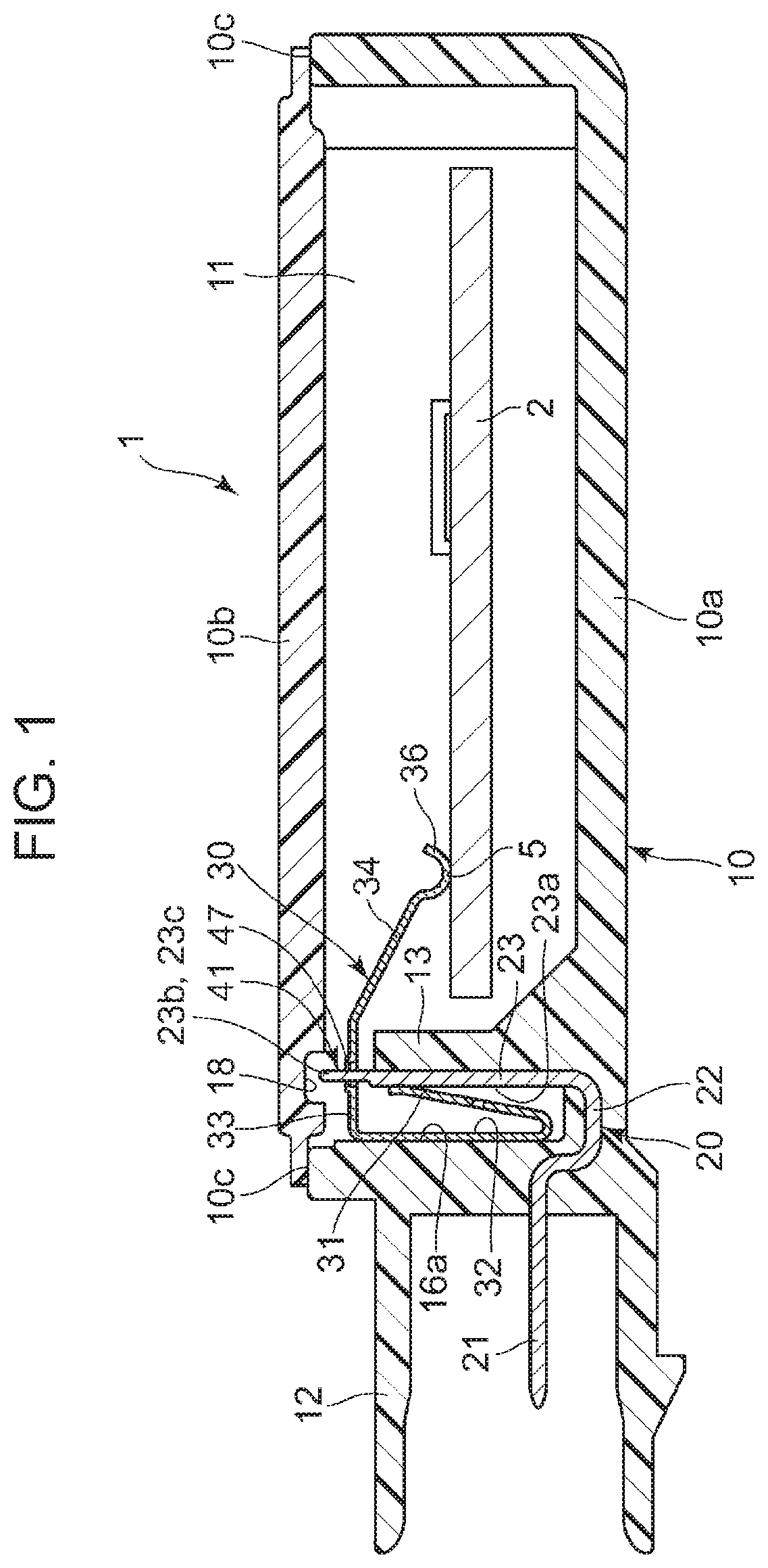
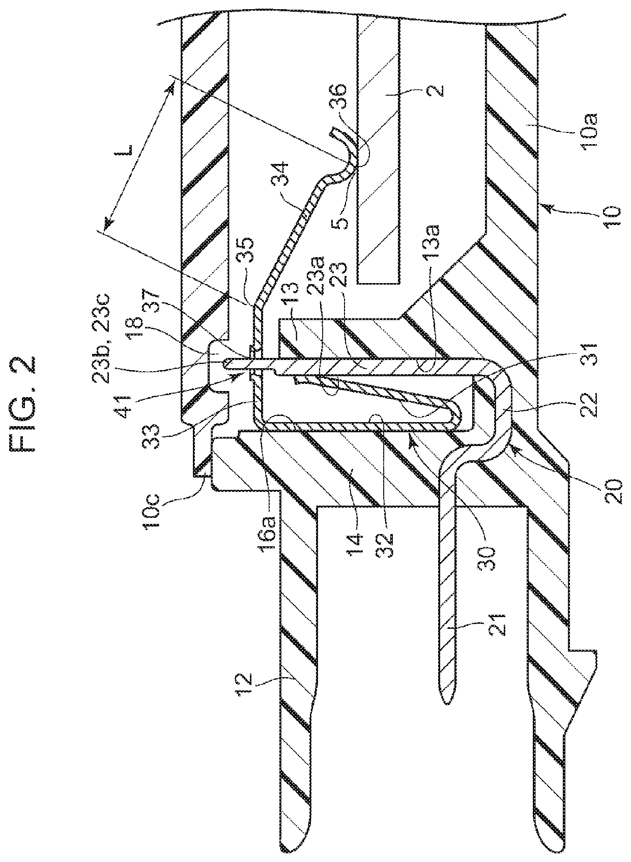
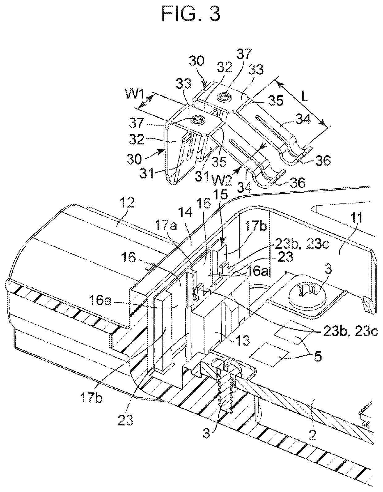
[0018]FIGS. 1 and 2 are each a cross-sectional view of an electronic device 1 in the present invention. FIG. 3 is an exploded perspective view of the electronic device 1, the drawing including a partial cross-section.

[0019]In this electronic device 1, a circuit board 2 is accommodated in internal space 11 in a case (cabinet) 10. As illustrated in FIG. 3, the circuit board 2 is fixed to the case 10 with fixing screws 3. On the circuit board 2, an acceleration sensor is mounted as a physical quantity sensor.

[0020]The physical quantity sensor is not limited to an acceleration sensor; the physical quantity sensor may be a pressure sensor, a humidity sensor, an angular velocity sensor, or the like. The electronic device 1 is for use in a vehicle. The electronic device 1 is attached to, for example, the axle or its support portion to detect acceleration exerted on the vehicle body. Therefore, the electronic device 1 is needed to be structured so that even if large acceleration is exerted ...

second embodiment

[0038]In the electronic device 101, illustrated in FIG. 5, in the present invention, a hole 33a and a stop piece 38b, which is cut upward from the hole 33a, may be formed integrally with the support piece portion 33 of the elastic conductive plate 30. The linkage end 23c, which is the top of the contact plate portion 23 of the fixed conductive plate 20, may be inserted into the hole 38a and the edge at the top of the stop piece 38b may be elastically pressed against the linkage end 23c and be stopped, forming a restricting portion 42 that prevents the support piece portion 33 from being deformed in a direction away from the fixed electrode portion 5 and also prevents the support piece portion 33 from moving.

third embodiment

[0039]In the electronic device 201, illustrated in FIG. 6, in the present invention, a pair of stop pieces 38b and 38c, which extend in mutually opposite directions, is formed in the hole 33a in the support piece portion 33. When the edges at the tops of the stop pieces 38b and 38c are elastically pressed against and are fitted to the front surfaces on both sides of the linkage end 23c inserted into the hole 33a, a restricting portion 43 is formed.

[0040]Also, as illustrated in FIGS. 5 and 6, the concave portion 18 is formed in the lower surface of the second case 10b, and the upper end of the linkage end 23c is inserted into the concave portion 18. Therefore, even if unexpected acceleration is exerted, the support piece portion 33 does not come off the linkage end 23c.


PUM

PropertyMeasurementUnit
bending angleaaaaaaaaaa
angleaaaaaaaaaa
angleaaaaaaaaaa

Abstract

Fixed conductive plates are buried in a case. In its internal space, a first contact surface, which is part of each fixed conductive plate, and a second contact surface, which is an inner surface of the case, are opposite to each other, and an elastic conductive plate is interposed in this opposing portion. The elastic conductive plate is structured so that, in a restricting portion, a support piece portion is fitted to the thin plate portion of the fixed conductive plate and that an elastic arm portion extends from the support piece portion.

Description

CLAIM OF PRIORITY[0001]This application is a Continuation of International Application No. PCT / JP2018 / 007081 filed on Feb. 27, 2018, which claims benefit of Japanese Patent Application No. 2017-048149 filed on Mar. 14, 2017. The entire contents of each application noted above are hereby incorporated by reference.BACKGROUND1. Field of the Disclosure[0002]The present disclosure relates to an electronic device that includes, in a case fixed conductive plates and elastic conductive plates pressed elastically against fixed electrode portions provided on a circuit board or the like on which a physical quantity sensor is mounted.2. Description of the Related Art[0003]An arrangement related to an electronic part in which external terminals (fixed conductive plates) and internal terminals (elastic conductive plates) are provided in a cabinet 1 is described in Japanese Unexamined Patent Application Publication No. 10-32107.[0004]This electronic part includes external terminals 2 fixed in the ...

Claims


Application Information

Patent Timeline
Patent Type & Authority Patents(United States)
IPC IPC(8): G01P15/08G01L19/14G01D11/24H01R13/15H01R13/66
CPCG01L19/14G01D11/245G01P15/08H01R13/15H01R13/6683G01L19/143H01R13/17H01R2201/26H01R13/2478H01R13/2457H01R13/4226H01R12/714H01R4/26H05K5/0069H05K5/0078G01P1/023
Inventor WAGA, SATOSHINAKAYAMA, KEISUKEHOSOGOE, JUNICHIKIKUCHI, SHINJISUZUKI, KAZUHIKO
Owner ALPS ALPINE CO LTD
Why Eureka
Try Eureka