
Clutching device of an automatic transmission

a technology of automatic transmission and clutch, which is applied in the direction of clutches, mechanical devices, couplings, etc., can solve the problems of fatigue accumulation and damage to the clutch, and achieve the effect of improving shifting responsiveness and precision control

Active Publication Date: 2020-05-05
HYUNDAI MOTOR CO LTD +1
View PDF16 Cites 0 Cited by
  • Summary
  • Abstract
  • Description
  • Claims
  • Application Information

AI Technical Summary

Benefits of technology

[0010]Various aspects of the present invention are directed to providing a clutching device of an automatic transmission having advantages of enhanced shifting responsiveness and precision controlling.
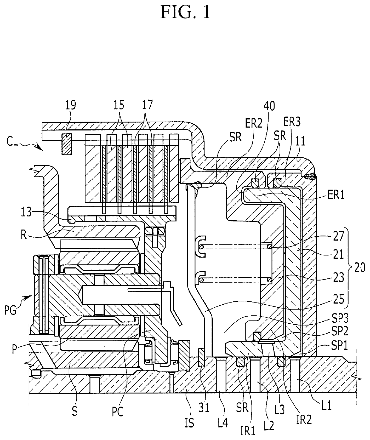
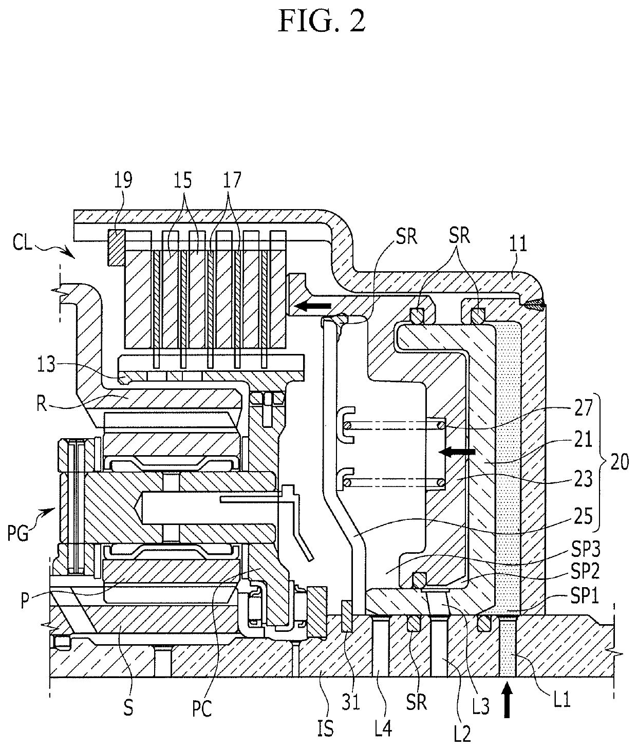
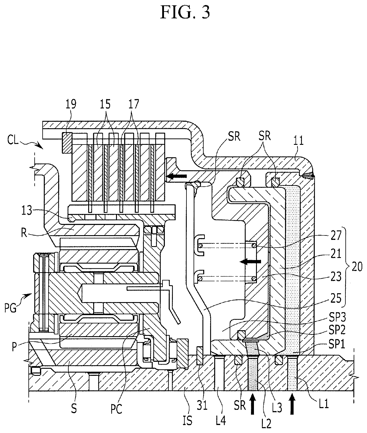
[0019]According to an exemplary embodiment of the present invention, dual pistons are used for operation of a clutch that transmits torque, improving shifting responsiveness due to better gap control between friction members, and also improving power delivery efficiency by ensuring a large engagement force.
[0020]Due to sequentially controlling of the first and second pistons, fatigue accumulation caused to the friction members may be significantly reduced, reducing possibility of damage to the clutch.
[0021]In the case of releasing the clutch, drag loss of friction members may be reduces while enhancing reliability of controlling the clutch by cancelling centrifugal force of fluid remaining in spaces between the pistons and the clutch drum, since the returning operation of the pistons initiated by a return spring is accelerated by the compensation hydraulic pressure supplied to a space between the spring retainer and the second piston.
[0022]Since a return spring initiates the returning operation of the pistons, unstableness of returning operation of pistons may be reduced by minimizing effect of unstableness of low initial hydraulic pressure when the hydraulic pressure is solely used for returning the pistons.

Problems solved by technology

Furthermore, a clutch may be damaged by fatigue accumulation by repeated application of a large engagement force and a rapid operating speed.

Method used


Image

  • Clutching device of an automatic transmission
  • Clutching device of an automatic transmission
  • Clutching device of an automatic transmission

Examples


Embodiment Construction

[0029]Reference will now be made in detail to various embodiments of the present invention(s), examples of which are illustrated in the accompanying drawings and described below. While the invention(s) will be described in conjunction with exemplary embodiments, it will be understood that the present description is not intended to limit the invention(s) to those exemplary embodiments. On the other hand, the invention(s) is / are intended to cover not only the exemplary embodiments, but also various alternatives, modifications, equivalents and other embodiments, which may be included within the spirit and scope of the invention as defined by the appended claims.

[0030]Hereinafter, an exemplary embodiment of the present invention will be described in detail with reference to drawings.

[0031]The drawings and description are to be regarded as illustrative in nature and not restrictive, and like reference numerals designate like elements throughout the specification.

[0032]In the following de...


PUM


Abstract

A clutching device of an automatic transmission may include a clutch drum connected to a first rotation element, a clutch connected to the clutch drum and a second rotation element, and a piston device to operate the clutch, wherein the piston device may include a first piston forming a first sealed space with the first rotation element and the clutch drum and moving toward the clutch by a hydraulic pressure supplied to the first sealed space, a second piston forming a second sealed space with the first piston and moving toward the clutch to directly press the clutch by a hydraulic pressure supplied to the second sealed space, a spring retainer disposed on the first rotation element and forming a third space with the second piston and the first rotation element, and a return spring stored in the third space and abutted by the spring retainer and the second piston.

Description

CROSS-REFERENCE TO RELATED APPLICATION[0001]The present application claims priority to Korean Patent Application No. 10-2017-0169263 filed on Dec. 11, 2017, the entire contents of which is incorporated herein for all purposes by this reference.BACKGROUND OF THE INVENTIONField of the Invention[0002]The present invention relates to a clutching device of an automatic transmission that connects or disconnects torque transmission between two rotation elements.Description of Related Art[0003]An environmentally-friendly technology of a vehicle is a core technology which controls survival of a future vehicle industry, and advanced vehicle makers have focused their energy on the development of an environmentally-friendly vehicle to achieve environmental and fuel efficiency regulations.[0004]For enhancing fuel consumption, a high efficiency engine, various approaches, such as a high efficiency transmission, a light-weight vehicle body, etc., are under investigation, and in the transmission fi...

Claims


Application Information

Patent Timeline
Patent Type & Authority Patents(United States)
IPC IPC(8): F16D25/06F16D25/0638F16D48/02F16H63/30F16D129/02
CPCF16D25/0638F16H63/3026F16D48/02F16D2048/0212F16D2300/14F16D2129/02F16H61/688F16D25/12F16D2048/0257F16D25/086
Inventor CHAE, MINHOPARK, JUHYEONSHIN, YONG UKJI, SEONGWOOK
Owner HYUNDAI MOTOR CO LTD
Learn More