Deployable and tracked solar array mechanism for nano-satellites

a solar array and nano-satellite technology, applied in the direction of transportation and packaging, cosmonautic vehicles, aircrafts, etc., can solve the problems of inability to “fix” any solar array panel or release mechanism, severely limited orbital average power (aop) and other problems

Active Publication Date: 2014-06-24
M M A DESIGN
View PDF28 Cites 38 Cited by
  • Summary
  • Abstract
  • Description
  • Claims
  • Application Information

AI Technical Summary

Problems solved by technology

While this yields the maximum area of cells, the structural architecture is not well suited to sun tracking and hence its Average Orbital Power (AOP) is severely limited due to non-optimal pointing during the majority of an orbit.
In addition, restraining the solar array panels during liftoff, flight, and positioning of the spacecraft and deploying the solar array panels when ready presents numerous problems.
Due to the fact that the spacecraft is orbiting the Earth, it is not possible to “fix” any solar array panels or release mechanisms after the spacecraft is in orbit.

Method used


Image

  • Deployable and tracked solar array mechanism for nano-satellites
  • Deployable and tracked solar array mechanism for nano-satellites
  • Deployable and tracked solar array mechanism for nano-satellites

Examples


Embodiment Construction

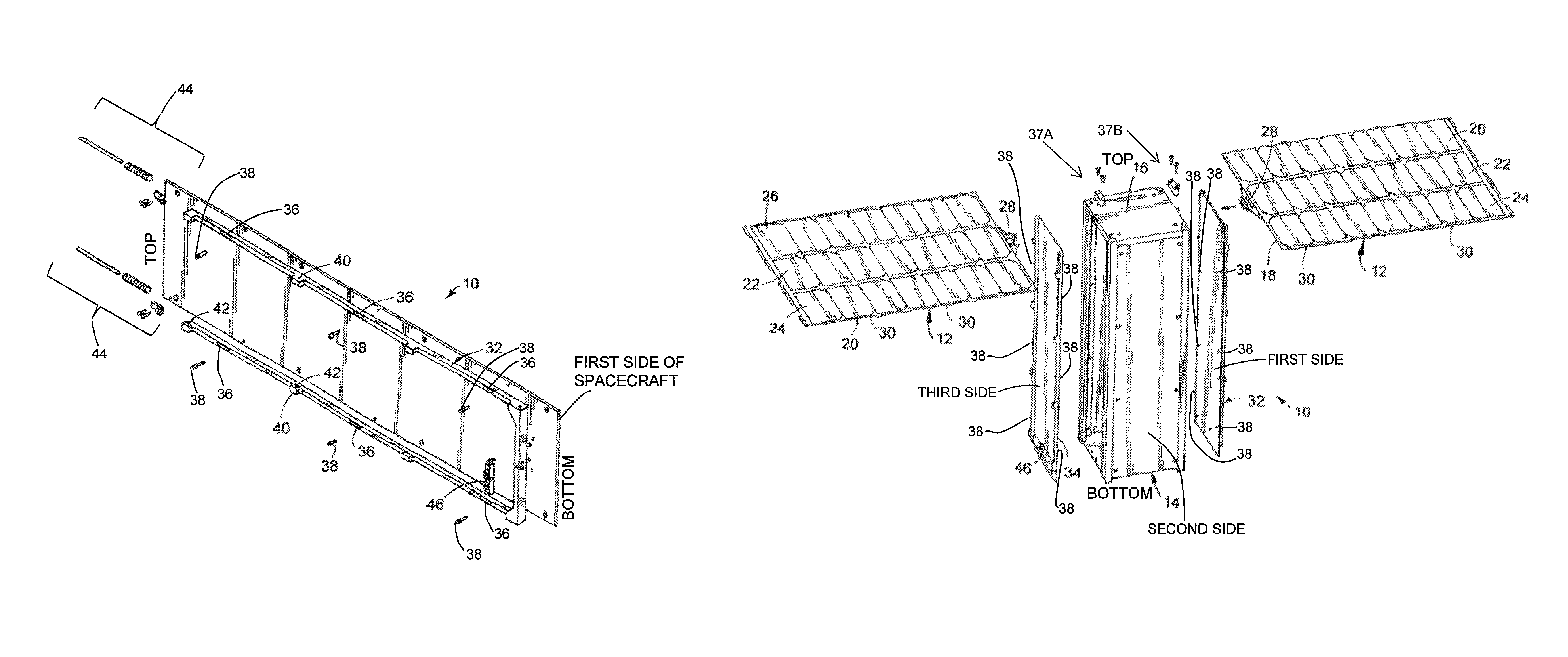
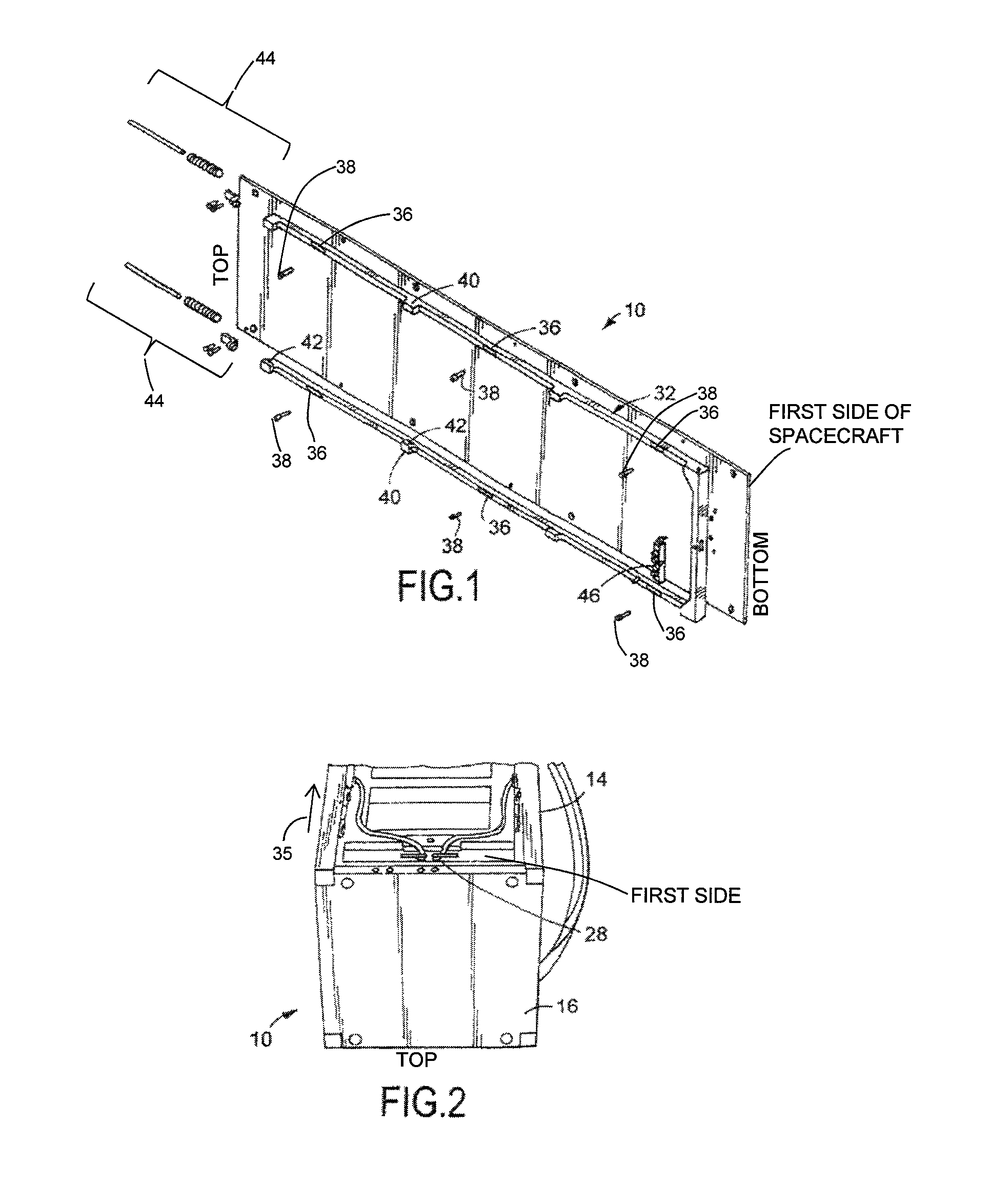
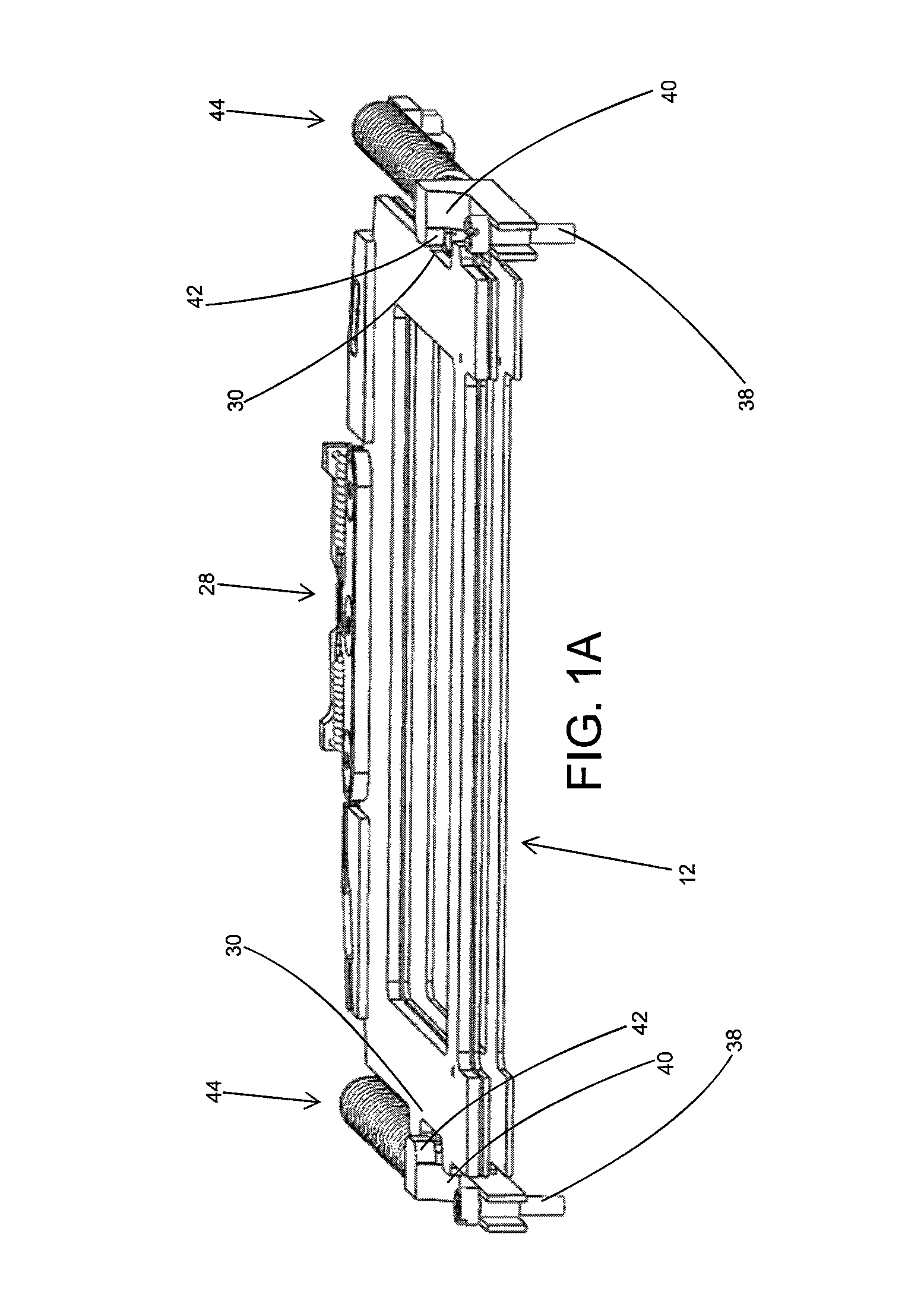
[0021]As illustrated in FIGS. 1, 1A, and 2-10, the present invention is a deployable and tracked solar array mechanism, indicated generally at 10, for restraining and releasing deployable solar panel arrays 12 on a spacecraft 14. The spacecraft 14 used with the mechanism 10 of the present invention is preferably a CubeSat spacecraft 14 although using the mechanism 10 on any type of spacecraft 14 is within the scope of the present invention. In addition, preferably, the solar panel arrays 12 are preferably constructed from a thin graphite-based composite panel stiffness and strength although using other types of solar panel arrays 12 is within the scope of the present invention.

[0022]The CubeSat spacecraft 14 has a four side surfaces, a top surface, and a bottom surface. Preferably, each side surface is substantially parallel to each opposite side surface and the top surface is substantially parallel to the bottom surface. Mounted on the top surface is a solar array drive assembly 16...


PUM


Abstract

A deployable and tracked solar array mechanism for restraining and releasing deployable solar panel arrays on a spacecraft is provided. The mechanism comprises a solar array drive mountable to the top side surface of the spacecraft. A solar panel array is pivotally attached to the solar array drive and positionable against the spacecraft. At least one notch is formed in at least one of the side edges of the solar panel array. A frame is slidably mounted to the spacecraft around the solar panel array. At least one tab extends from the frame over the solar panel array and releasably restrains the solar panel array. A spring mechanism urges the frame in a direction generally away from the solar array drive assembly. A release mechanism holds the frame against the force of the spring means wherein upon initiation of deployment, the release mechanism disintegrates allowing the spring means to slidably urge the frame in a general direction away from the solar array drive assembly thereby aligning the at least one notch with the at least one tab and releasing the solar panel array from against the spacecraft.

Description

[0001]The present application claims benefit of priority of provisional patent application Ser. No. 61 / 276,197, filed on Sep. 9, 2009, entitled “CubeSat Tracked Solar Array”.BACKGROUND OF THE INVENTION[0002]1. Field of the Invention[0003]This invention relates generally to a deployable and tracked solar array mechanism for nano-satellites and, more particularly, the invention relates to a deployable and tracked solar array mechanism for nano-satellites for a wrap-folded solar wing formed with a frame that restrains the lengthwise edges of a center panel of the solar wing on each side prior to deployment.[0004]2. Description of the Prior Art[0005]CubeSats are small spacecraft often 10 cm×10 cm×30 cm. Existing CubeSat deployable solar array panels hinge from all four 30 cm bus faces in a maximum power configuration. While this yields the maximum area of cells, the structural architecture is not well suited to sun tracking and hence its Average Orbital Power (AOP) is severely limited d...

Claims


Application Information

Patent Timeline
Patent Type & Authority Patents(United States)
IPC IPC(8): B64G1/44
CPCB64G1/44B64G1/222
Inventor HARVEY, THOMAS JEFFREYDEVITO, MATTHEW JOHN
Owner M M A DESIGN
Why Eureka
Try Eureka