

Flywheel mechanism for micro/nano-satellite
A micro-nano-satellite and flywheel technology, which is applied to aerospace vehicles, aircraft, motor vehicles, etc., can solve the problems of low development cost and the inability of traditional flywheels to meet mission requirements, etc.
- Summary
- Abstract
- Description
- Claims
- Application Information
AI Technical Summary
Problems solved by technology
Method used
Image

Examples
specific Embodiment approach 1
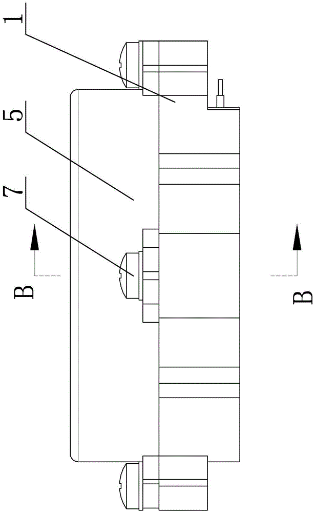
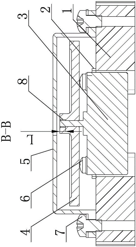
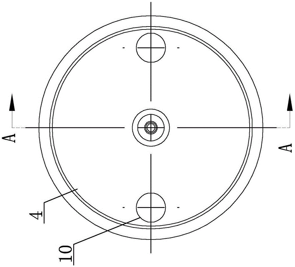
[0012] Specific implementation mode one: combine Figure 1-Figure 5 Describe this embodiment mode, a kind of flywheel mechanism for micro-nano satellite described in this embodiment mode, it comprises motor support 1, shock pad 2, brushless motor 3, wheel body 4 and protective cover 5; Shock pad 2 is Rectangular frame, the through hole for installing the motor is processed on the rectangular frame, the shock pad 2 is installed on the motor bracket 1, the brushless motor 3 is installed on the motor bracket 1, the shock pad 2 is set on the brushless motor 3 and the motor Between the brackets 1 , the wheel body 4 is set on the output end of the brushless motor 3 rotating shaft, the protective cover 5 is installed on the motor bracket 1 , and the protective cover 5 is fastened on the outside of the wheel body 4 .
specific Embodiment approach 2
[0013] Specific implementation mode two: combination Figure 1-Figure 2 Describe this embodiment, a flywheel mechanism for micro-nano satellites described in this embodiment, the shock-absorbing pad 2 is a shock-absorbing pad made of natural rubber, and the shock-absorbing pad 2 is installed on the motor bracket 1 through silicon rubber Above, other structures are the same as those in the first embodiment.
specific Embodiment approach 3
[0014] Specific implementation mode three: combination Figure 1-Figure 2 Describe this embodiment, a flywheel mechanism for micro-nano satellites described in this embodiment, it also includes a plurality of first pan head screws 6 and a plurality of second pan head screws 7; the brushless motor 3 passes through a plurality of second pan head screws A pan head screw 6 is fixedly installed on the motor bracket 1, and the protective cover 5 is fixedly installed on the motor bracket 1 through a plurality of second pan head screws 7, and other structures are the same as in the first embodiment.
PUM
 Abstract
Description
Claims
Application Information