Flexible cable connector assembly

a connector and flexible technology, applied in the direction of electrical equipment, coupling device connections, printed circuits, etc., can solve the problems of easy bending of the outgoing terminal of the cable, complicated manual operation of the cable assembly process, and easy bending of the cable, so as to prevent abrasion wear, prevent bending, and avoid damage to the bending member

Active Publication Date: 2014-06-24
BING XU PRECISION
View PDF67 Cites 20 Cited by
  • Summary
  • Abstract
  • Description
  • Claims
  • Application Information

AI Technical Summary

Benefits of technology

[0008]One object of the present invention has the benefit that a bending member is defined by the protective film and the front-end of the flexible cable, wherein the protective film provides proper protection for the bending member so as to avoid damage to the bending member while it is bent, and prevent abrasive wear between the flexible cable and the insulative body.
[0009]Another object of the present invention has the benefit that the protective film is a conductive shielding film containing high conductive materials, and when a plurality of conductors of the flexible cable are transmitting signals, the protective film provides proper shielding to eliminate the crosstalk among the conductors as well as reduces the electrical interference from the surrounding.

Problems solved by technology

However, a conventional cable connector assembly requires specialized cable management and processes for the cable to be welded to the conductive terminals, and the cable assembly process is complicated to be operated manually and difficult to be manufactured, and the cable management equipment and the processes are adding to the overall cost of manufacture, thus, improving the structure is necessary.
Besides, the outgoing terminal of the cable is held by the cover and the insulative body, therefore, the outgoing terminal of the cable is easily bent and requires proper protection to prevent damage while the cable is bent.

Method used


Image

  • Flexible cable connector assembly
  • Flexible cable connector assembly
  • Flexible cable connector assembly

Examples


second embodiment

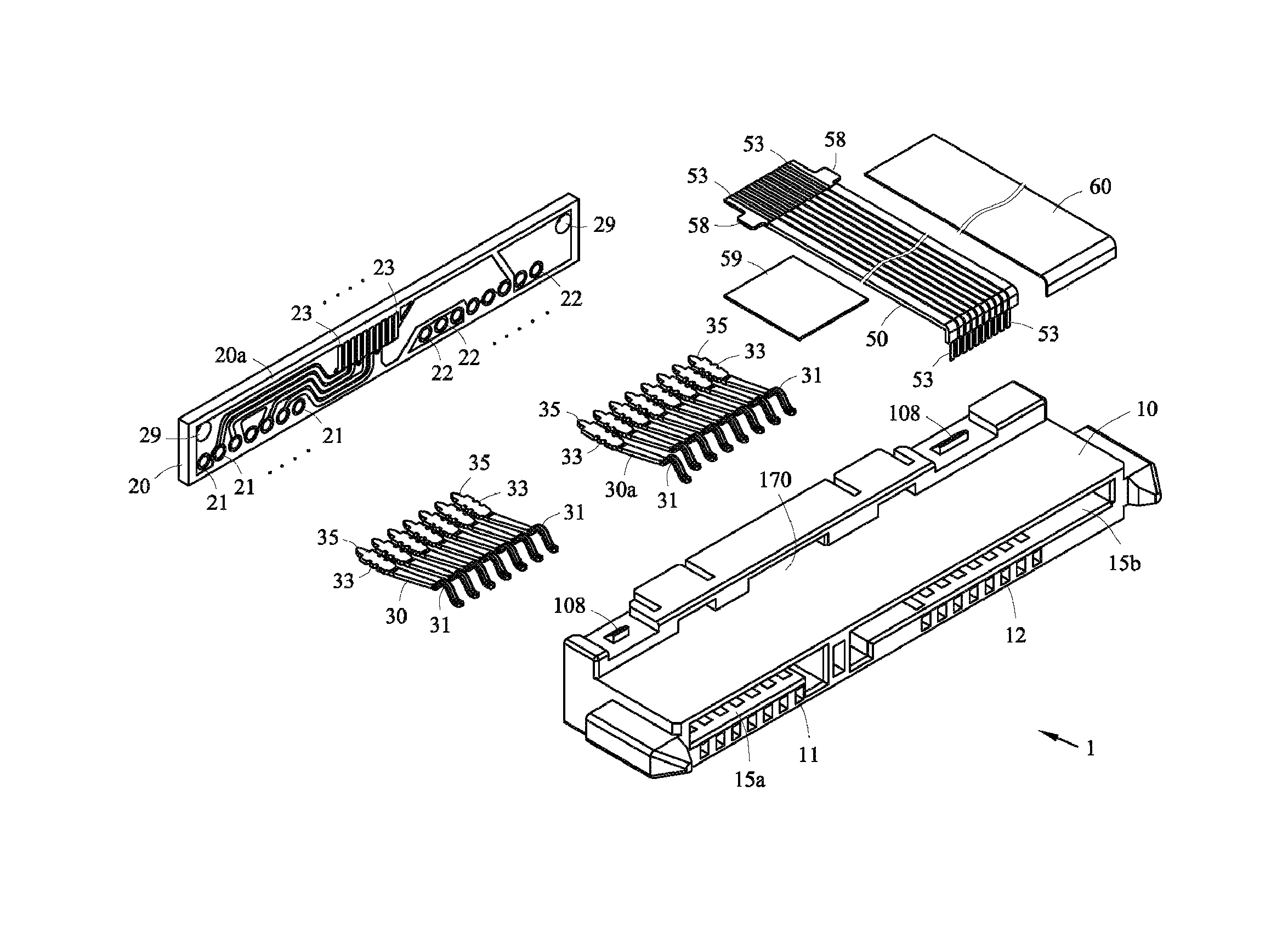
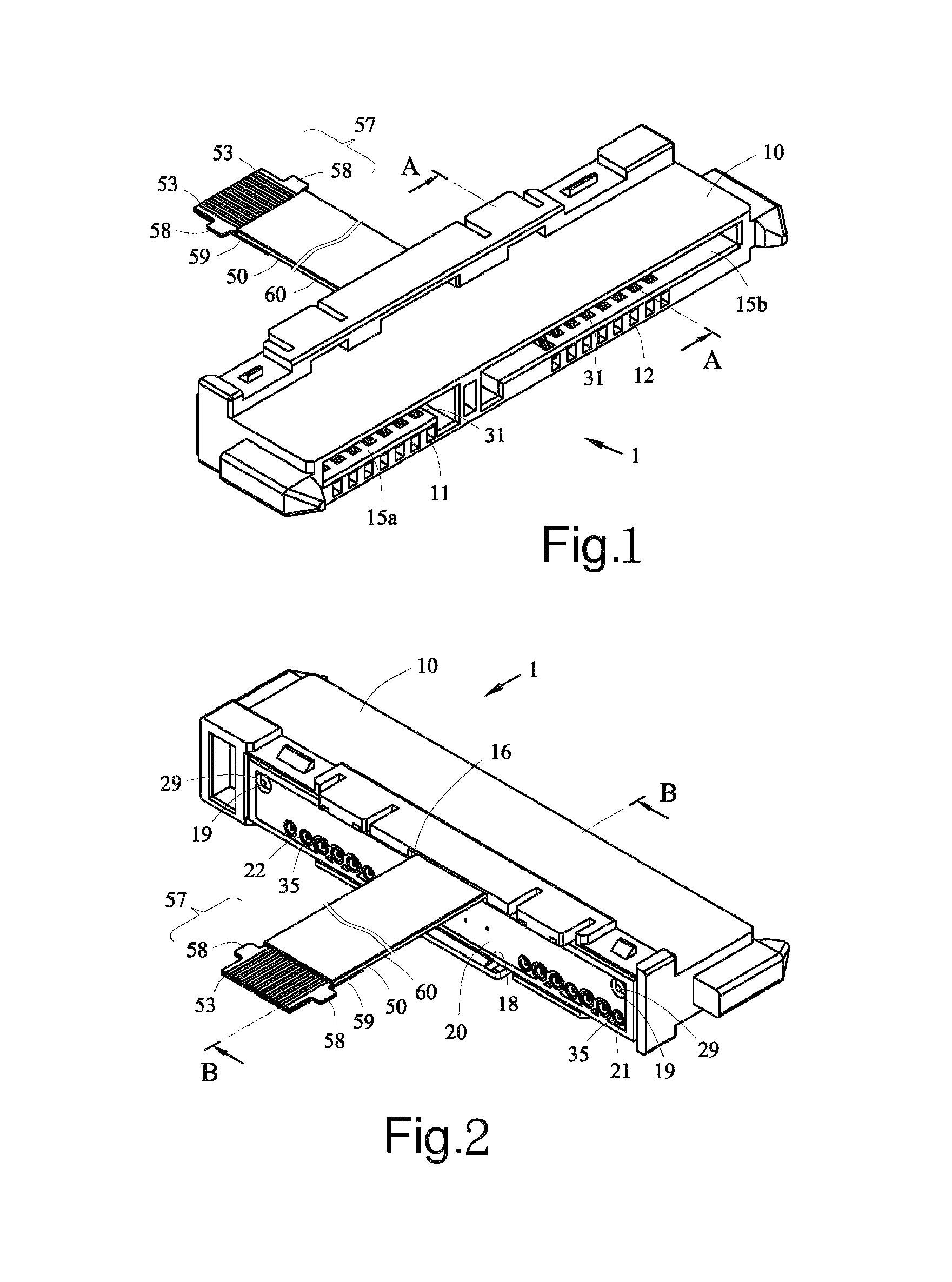
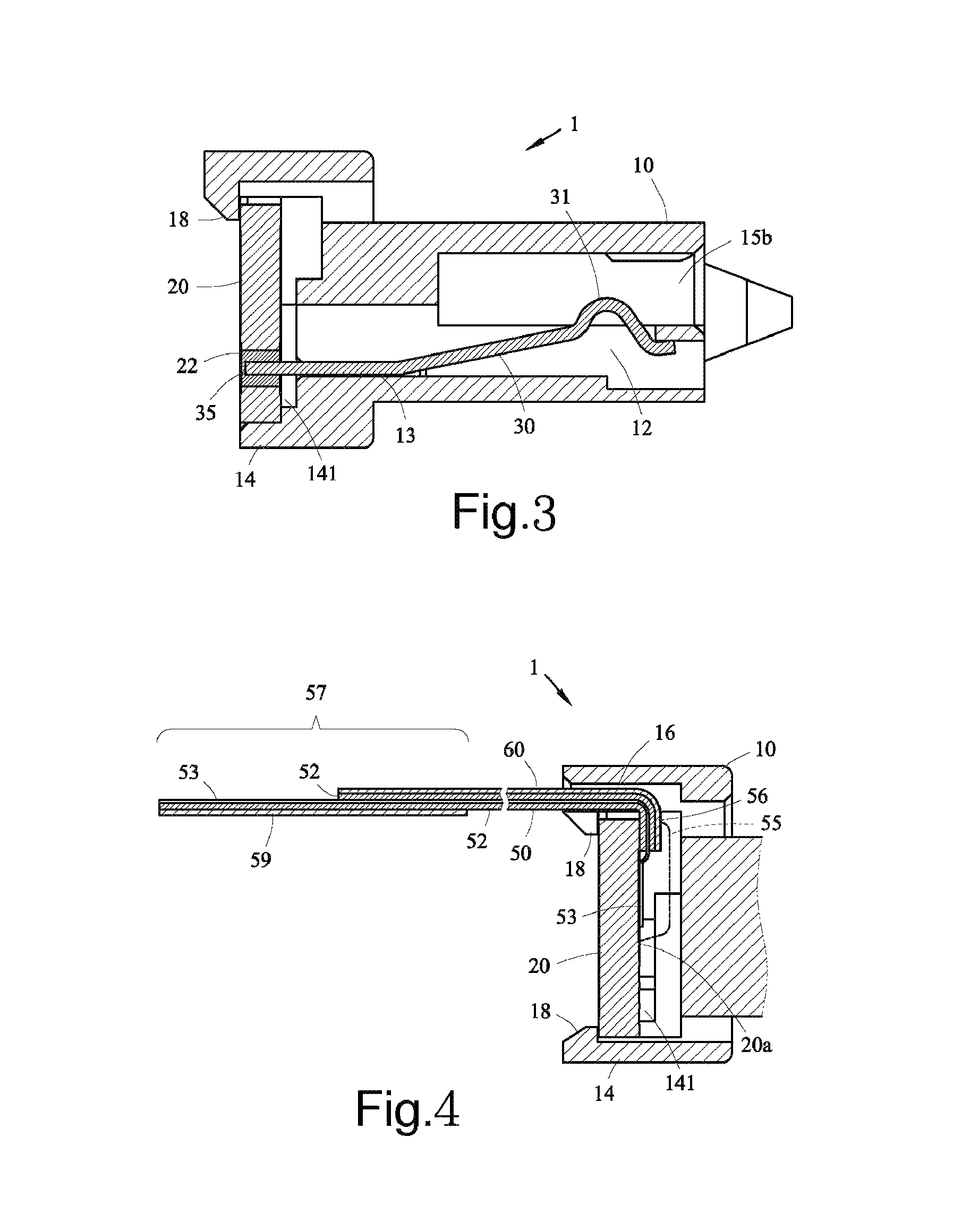
[0067]Please refer to FIGS. 7 to 9, in a second embodiment according to the present invention, a pair of lugs 58 is formed at the rear-end 57 of the flexible cable 50, and the rear-end 57 of the flexible cable 50 is adhered to a supporting plate 59; wherein the rear-end 57 of the flexible cable 50 is electrically connected to an FFC connector 90 or an FPC connector (not shown), and the rear-end 57 of the flexible cable 50 is fixed to the FFC connector 90 or the FPC connector using two lugs 58 and the supporting plate 59. Besides, the insulative body 10 is further disposed with a pull-string 17; wherein the pull-string 17 is inserted into a rectangular hole 170 of the insulative body 10 and through the wire slot 16 to be exposed.

third embodiment

[0068]Please refer to FIGS. 10 to 11, in a third embodiment according to the present invention, the conductive parts 23 are disposed at the interior side surface 20a of the PCB 20, and the exterior side surface 20b of the PCB 20 comprises a grounding member 24, and the welding parts 211, 214 and 217 of the first welding parts 21 and the conductive parts 231, 234 and 237 of the plurality of conductive parts 23 are electrically connected to the grounding member 24, the welding parts 212, 213, 215 and 216 of the first welding parts 21 are electrically connected to the conductive parts 232, 233, 235 and 236 of the conductive parts 23; wherein the welding parts 221, 222, 223, 227 and 228 of the second welding parts 22 are electrically connected to the grounding member 24 jointly, and the welding parts 224, 225 and 226 of the second welding parts 22 are electrically connected to the conductive parts 238, 239 and 230 of the plurality of conductive parts 23 jointly. Alternatively, each of t...

fifth embodiment

[0070]Please refer to FIGS. 18 to 23, a connector assembly 1 in a fifth embodiment according to the present invention is largely the same to that in the preferred embodiment, except for a cover 80 which is engaged to the rear-end 14 of the insulative body 10; wherein the cover 80 is engaged to at least a pair of hooks of the insulative body 10 using at least a pair of fixing parts 81, and a gap 86 is defined by the cover 80 and the insulative body 10, whereby the flexible cable 50 and the protective film 60 are extended outwardly. Besides, when the rear-ends 35 of the first terminals 30 and the second terminals 30a are extended beyond the exterior side surface 20b of the PCB 20, the cover 80 comprises a pair of grooves 85 to accommodate the extended rear-ends 35 of the first terminals 30 and the second terminals 30a. Additionally, when the welding materials of the first wielding parts 21 and the second welding parts 22 are extended beyond the exterior side surface 20b of the PCB 20,...


PUM


Abstract

Disclosed is a flexible cable connector assembly which comprises an insulative body, a PCB, a flexible cable and a protective film. The insulative body comprises at least a plurality of first terminals, the PCB is fixed at the rear-end of the insulative body, the protective film is adhered to the insulative layer of the flexible cable, and the flexible cable and the first terminals are electrically connected through the PCB; wherein a wire slot is defined by the PCB and the insulative body, whereby the protective film and the flexible cable are passed outwardly therethrough.

Description

CROSS REFERENCE TO RELATED APPLICATION[0001]This application claims the priority of Taiwanese Patent Application No. 101212551, filed on Jun. 29, 2012 in the TIPO (Intellectual Property Office), the disclosure of which is incorporated herein in their entirety by reference.BACKGROUND OF THE PRESENT INVENTION[0002]1. Field of the Invention[0003]The present invention relates to a flexible cable connector assembly, and particularly relates to a connector assembly with a printed circuit board (PCB), whereby the PCB is electrically connected to a flexible cable, and the flexible cable is a flexible flat cable (FFC) or a flexible print circuit (FPC).[0004]2. Description of the Prior Art[0005]Conventional technologies, such as the Taiwan patent No. M348367 “A cable connector assembly” (and its related foreign patents are CN patent publication No. CN201266719 and U.S. Pat. No. 7,815,459), the cable connector comprises an insulative body, a plurality of conductive terminals housed in the insu...

Claims


Application Information

Patent Timeline
Patent Type & Authority Patents(United States)
IPC IPC(8): H01R12/00
CPCH01R12/77H01R12/62H01R13/6461H01R13/6594H01R13/6658
Inventor CHEN, CHIH-JUNG
Owner BING XU PRECISION
Why Eureka
Try Eureka