
Electrical connector with locking mechanism

a technology of locking mechanism and electric connector, which is applied in the direction of coupling device connection, coupling parts engagement/disengagement, electrical apparatus, etc., can solve the problems of increasing the load acting on increasing the risk of breaking the supporting point portion, so as to reduce the impact transmitted to the first supporting portion, the effect of high degree of flexibility

Active Publication Date: 2014-06-24
JST MFG CO LTD
View PDF9 Cites 11 Cited by
  • Summary
  • Abstract
  • Description
  • Claims
  • Application Information

AI Technical Summary

Benefits of technology

This patent describes a technical solution to prevent breakage of a supporting point on a connector. By making the supporting point into a curved shape with a large radius of curvature and no sharp points, the solution reduces stress concentration and prevents breakage. However, this may increase the size of the connector. Additionally, the patent proposes arranging the first support portions at positions spaced in the width direction from the middle of the lock main body, which helps absorb some of the load acting on the lock main body and prevent excessive input to the first support portion, further increasing the reliability of preventing damage to the connector.

Problems solved by technology

Moreover, the greater the number of contacts provided in the wired locking connector, the longer the length of the operating portion, and the heavier the load acting on the supporting point portion.
For these reasons, for example, during manufacturing of the wired connector, when an impact is accidentally applied to the operating portion in the step of inserting the wires into the housing of the connector, this impact is directly transmitted to the supporting point portion, and there is a risk that the supporting point portion may be broken.
Moreover, when an impact is accidentally applied to the operating portion during transport of the wired connector, there is a risk that the supporting point portion may be broken as well.
However, in this case, the buffer material is necessary and packing of the housing in the buffer material is also necessary, and thus, the costs, such as the packing cost, related to the wired connector are expensive.
In a state in which the tensile force acts on the wires in this manner, if a finger or the like inadvertently comes into contact with the operating portion and the operating portion swings even slightly, the locking engagement portion also swings, resulting in disengagement of the locking claw from the engagement claw portion, and so there is a possibility that the wired connector may be disconnected.

Method used


Image

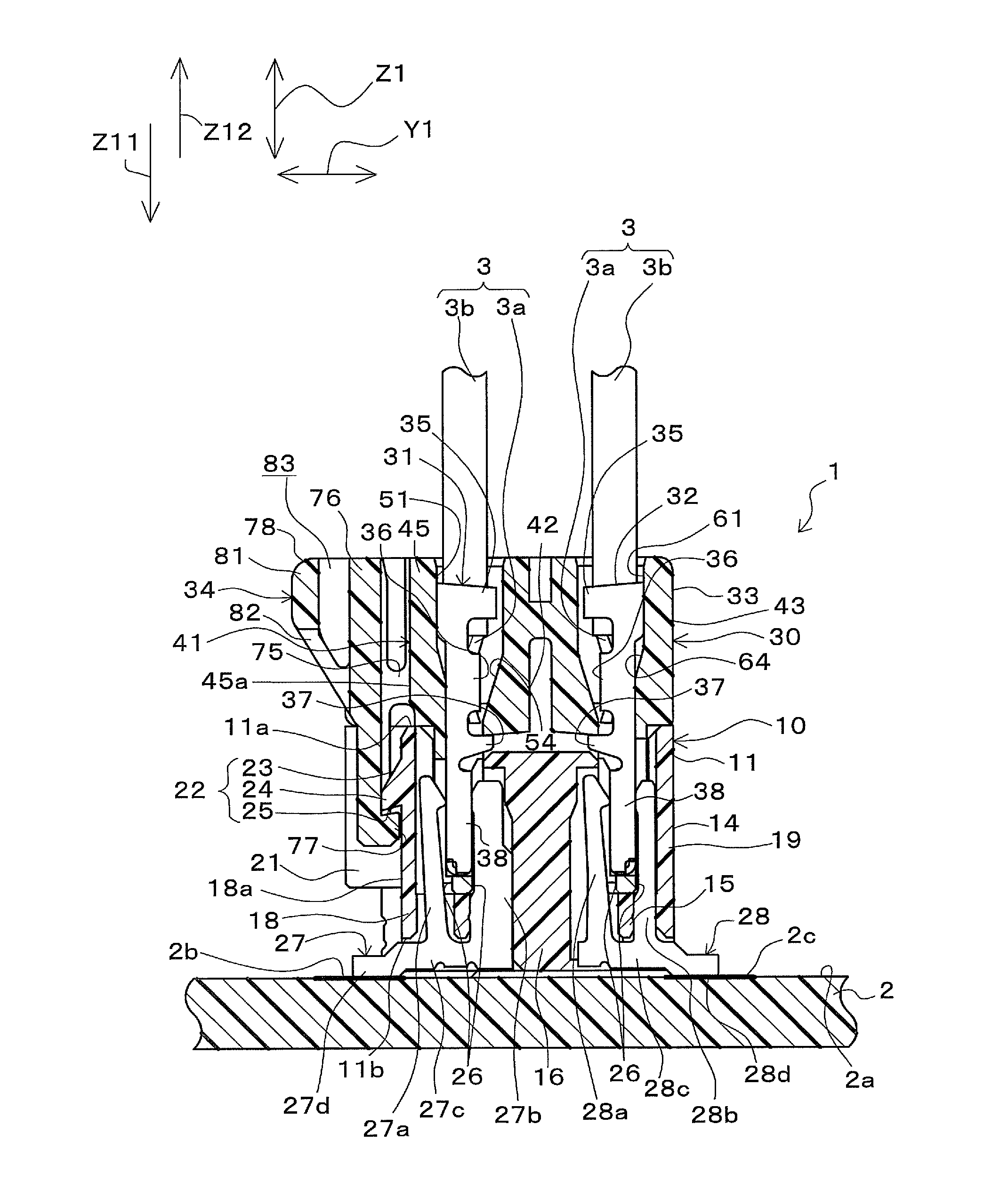
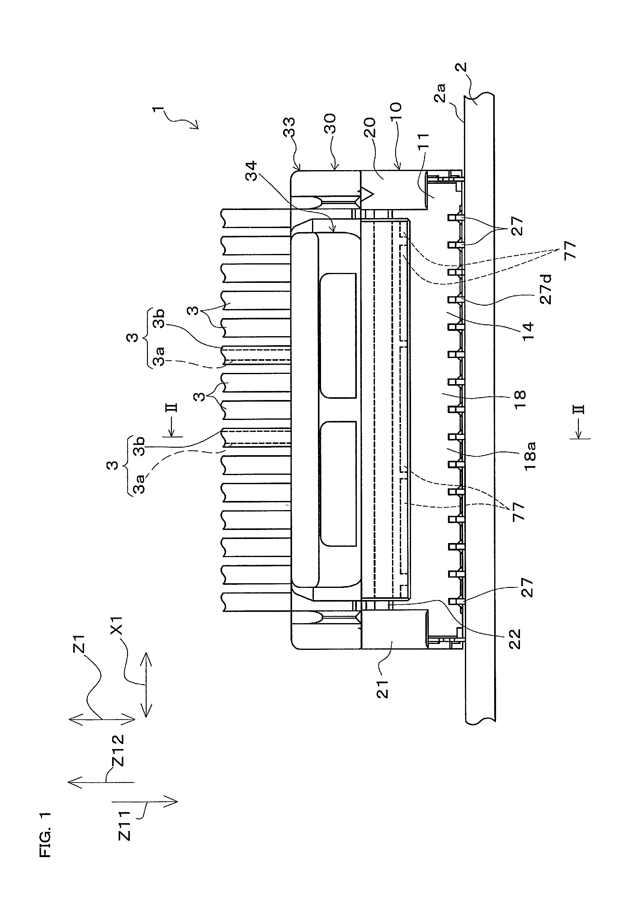
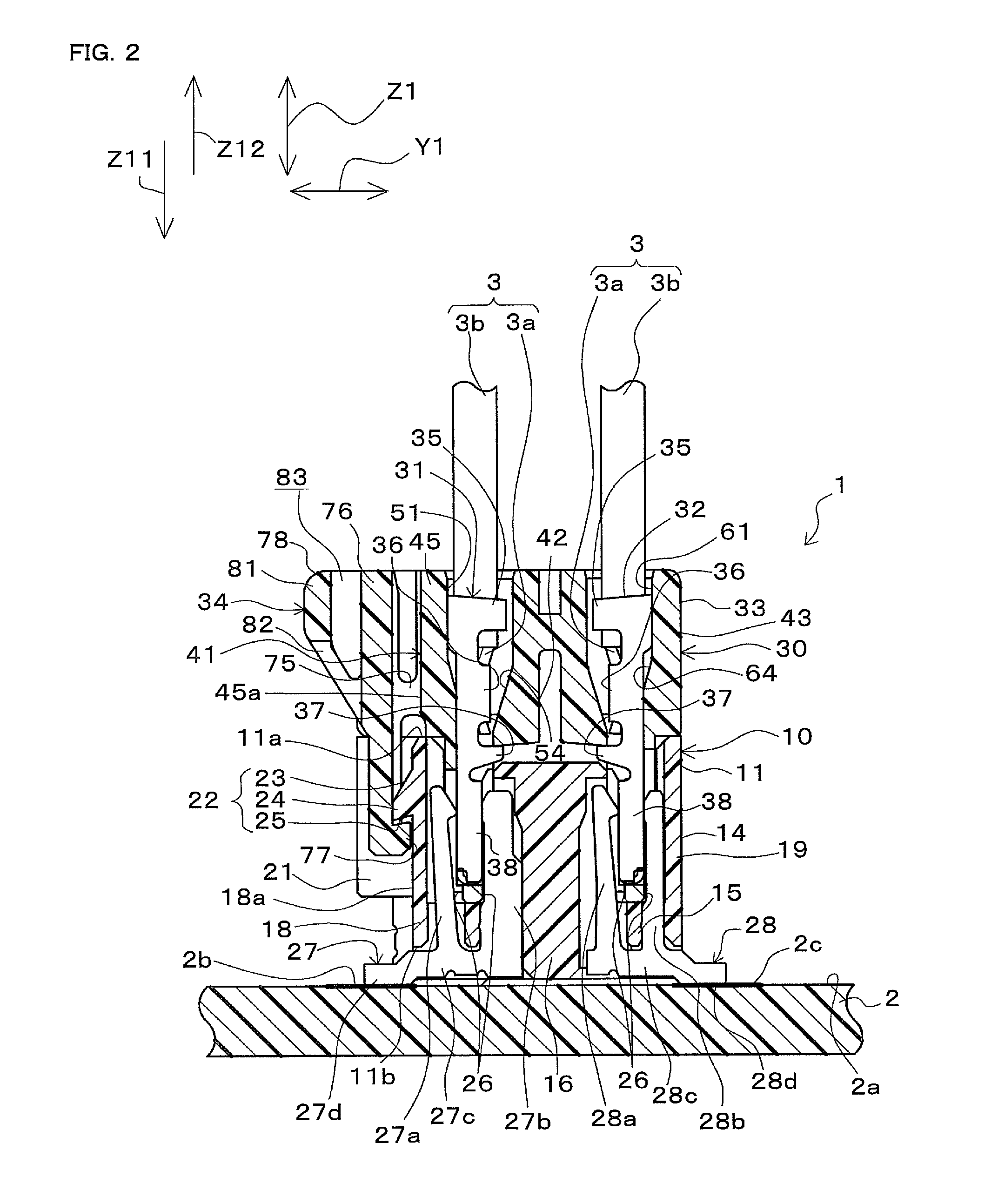
  • Electrical connector with locking mechanism
  • Electrical connector with locking mechanism
  • Electrical connector with locking mechanism

Examples


example

[0138]With regard to an electrical connector with a locking mechanism having the same shape as the connector 30 shown in FIG. 7A, a simulation was performed using a computer to examine a relationship between the displacement amount of the operating portion main body and the displacement amount of each portion of the locking mechanism. FIGS. 13A to 13C show the results.

[0139]FIG. 13C is a perspective view showing the displacement amount of each portion of the locking mechanism when the engagement tabs of the locking mechanism are displaced in a direction in which they are raised relative to the housing by a minimum amount required to disengage the engagement tabs from the engagement portion of the counterpart electrical connector. That is to say, FIG. 13C shows a state in which the engagement tabs of the lock main body have been raised to the highest level. FIG. 13B is a perspective view showing the displacement amount of each portion of the locking mechanism when a load equal to two...


PUM


Abstract

An electrical connector with a locking mechanism includes a housing and a locking mechanism provided in the housing. The locking mechanism includes a first support portion extending from the housing, a lock main body supported by the first support portion in a swingable manner, an engagement tab capable of engaging with and disengaging from an engagement portion provided in a counterpart electrical connector according to swinging of the lock main body, and an operating portion arranged to be pressed in order to swing the lock main body. The operating portion includes a second support portion provided in the lock main body and an operating portion main body supported by the lock main body via the second support portion. A space for allowing the operating portion main body to bend is formed between the operating portion main body and the lock main body.

Description

CROSS-REFERENCE TO RELATED APPLICATION[0001]This application claims priority to Japanese Patent Application No. 2011-216497. The entire disclosure of Japanese Patent Application No. 2011-216497 is hereby incorporated herein by reference.BACKGROUND OF THE INVENTION[0002]1. Field of the Invention[0003]The present invention relates to an electrical connector with a locking mechanism, the electrical connector being equipped with a locking mechanism for inhibiting disconnection of the electrical connector from a counterpart electrical connector.[0004]2. Description of Related Art[0005]As disclosed in, for example, JP 2009-230895A, wired connectors to be joined to connectors mounted on circuit boards have locking mechanisms that prevent disconnection from the connectors mounted on the circuit boards. A wired connector disclosed in JP 2009-230895A has a housing made of a synthetic resin and a plate-like locking engagement portion provided in the housing. The locking engagement portion is s...

Claims


Application Information

Patent Timeline
Patent Type & Authority Patents(United States)
IPC IPC(8): H01R13/62
CPCH01R13/6272
Inventor KUBO, TSUKASASAWADA, NORIKAZU
Owner JST MFG CO LTD
Learn More