
Multirole circuit element capable of operating as variable resonator or transmission line and variable filter incorporating the same

a multi-role circuit and variable filter technology, applied in the direction of resonators, electrical devices, waveguides, etc., can solve the problems of large devices, substantially changed, and radio communication devices that cannot serve the function under other than central frequency combinations, so as to achieve the effect of changing bandwidth and bandwidth

Inactive Publication Date: 2014-06-24
NTT DOCOMO INC
View PDF13 Cites 2 Cited by
  • Summary
  • Abstract
  • Description
  • Claims
  • Application Information

AI Technical Summary

Benefits of technology

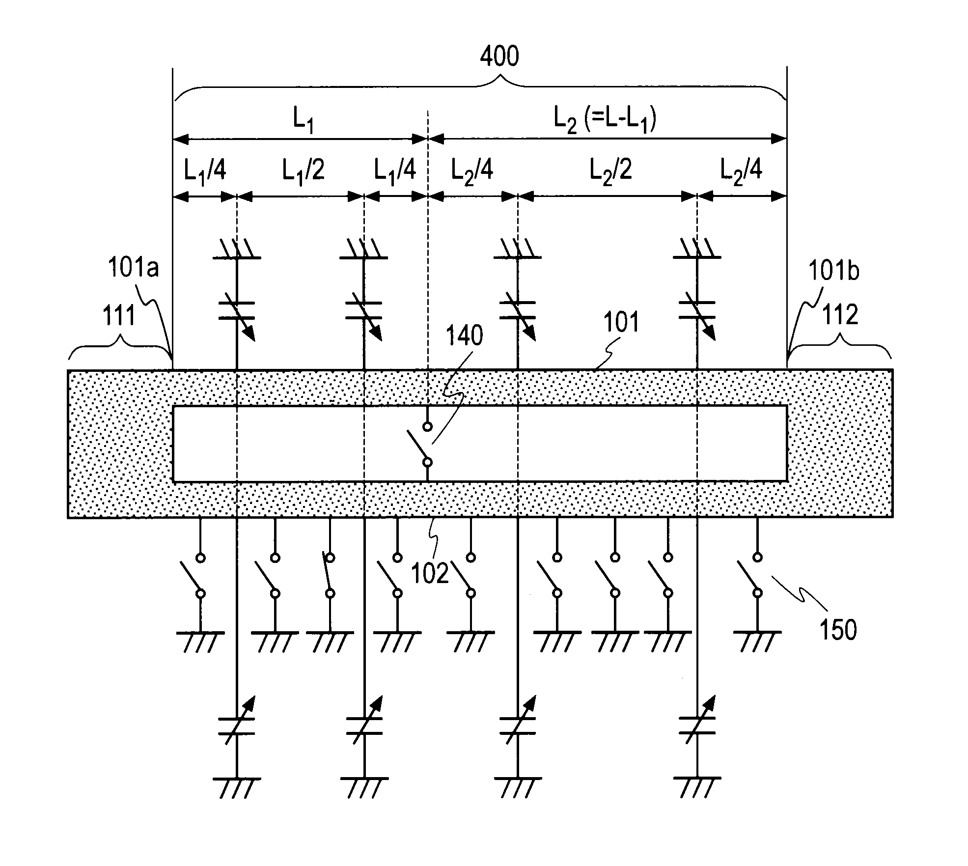
[0018]The multirole circuit element according to the present invention can function as a transmission line and a variable resonator (or a variable filter) depending on the selective setting of the on / off state of the switch circuits. The variable resonator according to the present invention can substantially change the bandwidth by selecting one of a plurality of switch circuits to be turned on. A variable filter capable of substantially changing the bandwidth can be provided by using the variable resonator. In the case where the variable resonator has a switch that links the two transmission lines to each other, the resonance frequency can be arbitrarily changed independently of the bandwidth by selectively turning on and off the switch. A variable filter not only capable of substantially changing the bandwidth but also capable of arbitrarily changing the central frequency independently of the bandwidth, can be provided by using the variable resonator. In the case where the variable filter has a plurality of switches that link the two transmission lines to each other, not only the bandwidth and the central frequency but also the number of stages of the filter can be independently changed by appropriately selecting the switches to be turned on.

Problems solved by technology

As a result, the device becomes large.
In addition, according to this method, the radio communication device cannot serve the function under conditions other than the combinations of central frequency and bandwidth of the conventionally mounted filters.
However, the extent to which the central frequency of the filter can be changed is as small as about 1% to 2% because of the limitation by the characteristics of the piezoelectric element, and thus, the bandwidth can be changed only to similar extent and cannot be substantially changed.
In addition, according to the prior art, circuit elements (such as a resonator and a filter) in a circuit have their respective fixed roles, and it is difficult to make the whole or some of the circuit elements function as components (such as a transmission line) other than themselves.

Method used


Image

  • Multirole circuit element capable of operating as variable resonator or transmission line and variable filter incorporating the same
  • Multirole circuit element capable of operating as variable resonator or transmission line and variable filter incorporating the same
  • Multirole circuit element capable of operating as variable resonator or transmission line and variable filter incorporating the same

Examples


Embodiment Construction

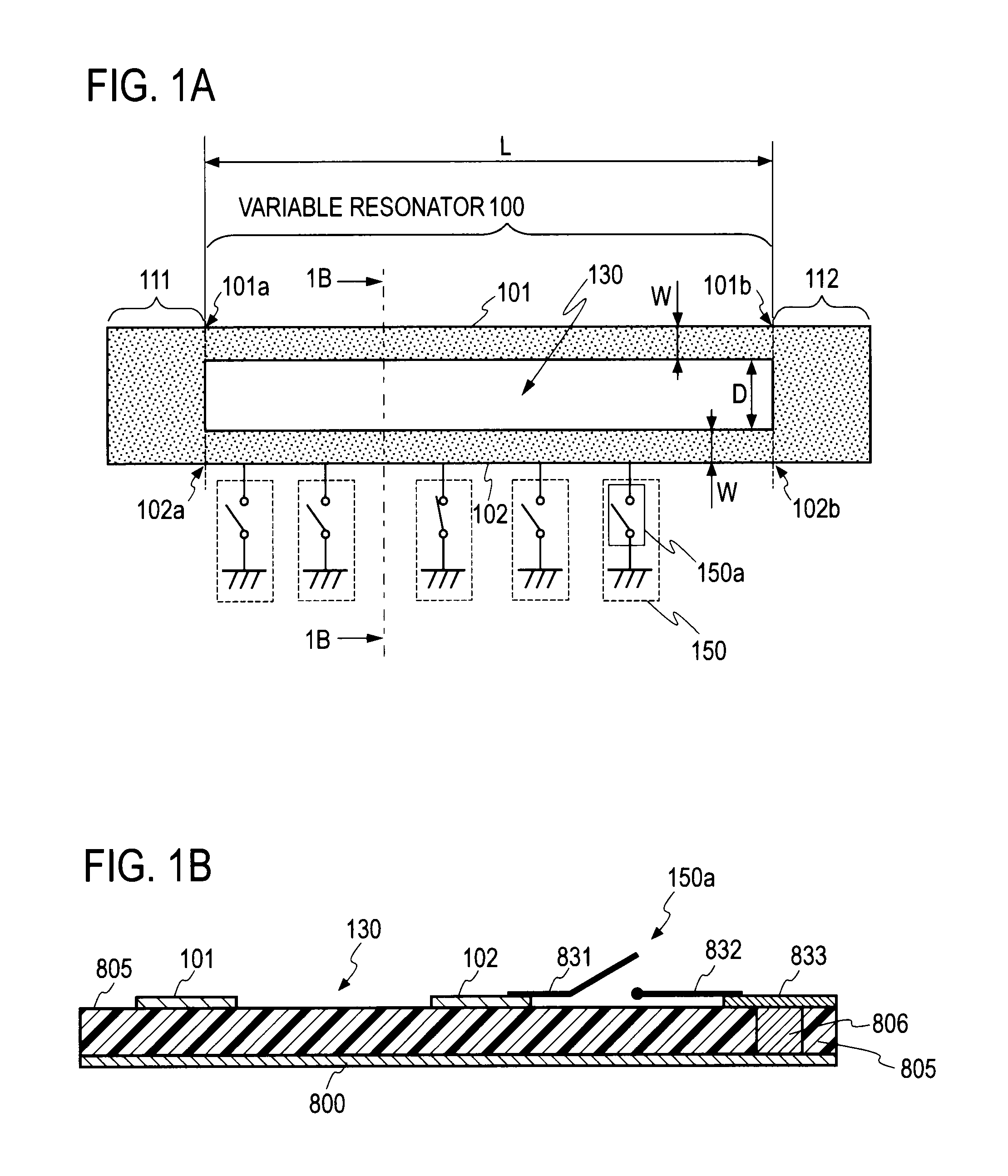
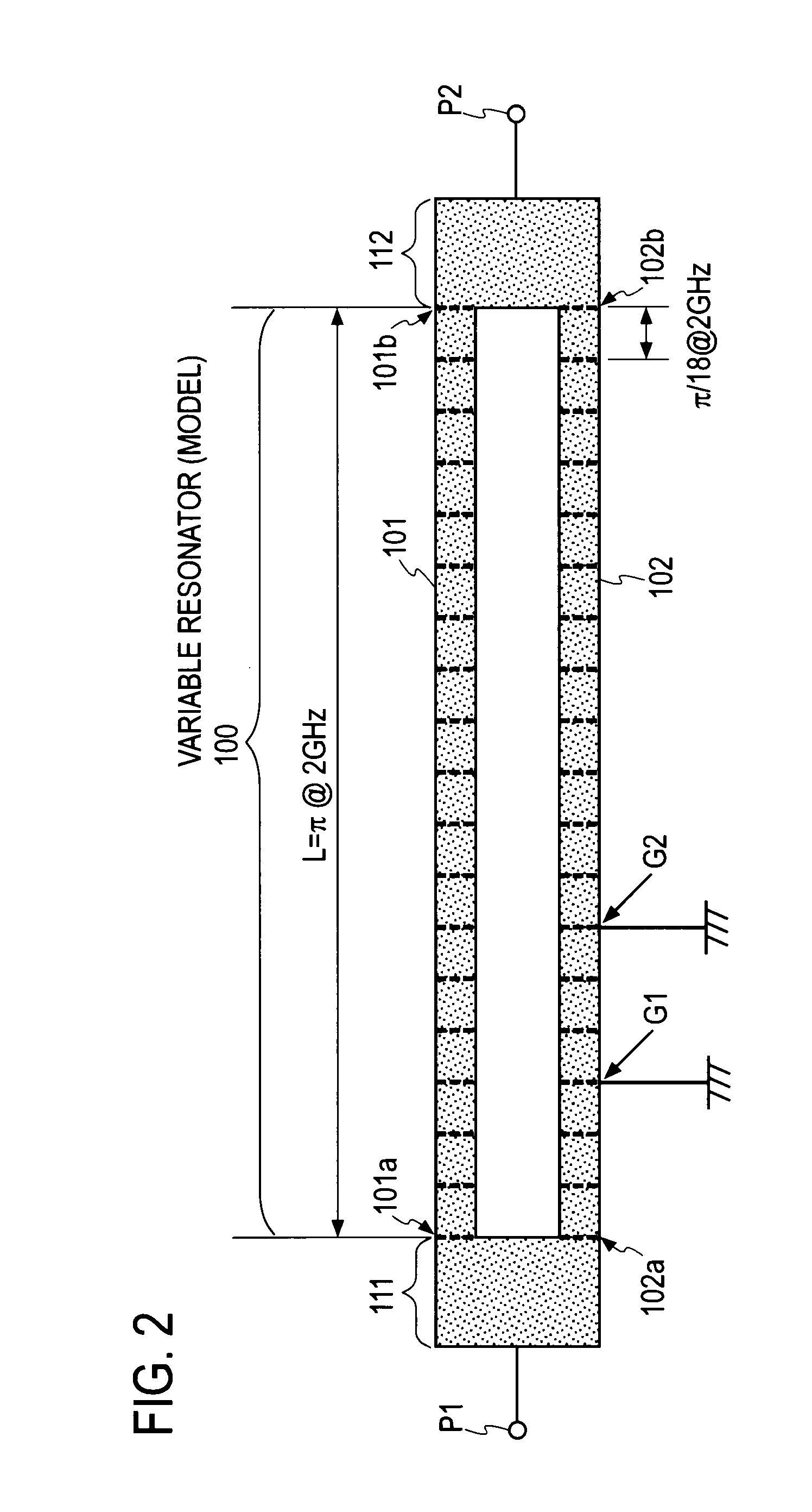
[0058]FIG. 1A shows a variable resonator 100 having a microstrip line structure according to an embodiment of the present invention, and FIG. 1B is a cross-sectional view of the variable resonator 100 taken along the line 1B-1B. The variable resonator 100 comprises two transmission lines 101 and 102 and a plurality of switch circuits 150. In the embodiment shown in FIG. 1A, the two transmission lines 101 and 102 having a rectangular shape are formed on a dielectric substrate 805. The first transmission line 101 is connected at one end 101a thereof to an input line 111 formed on the dielectric substrate 805 and at the other end 101b to an output line 112 formed on the dielectric substrate 805. The second transmission line 102 is connected at one end 102a thereof to the input line 111 and at the other end 102b to the output line 112. The two transmission lines 101 and 102 are made of a conductor, such as metal, and formed on the top surface of the dielectric substrate 805. A grounding...


PUM


Abstract

A variable resonator includes a first transmission line 101, a second transmission line 102 and a plurality of switch circuits 150. The electrical length of the first transmission line 101 is equal to the electrical length of the second transmission line 102. The characteristic impedance for the even mode of the first transmission line 101 is equal to the characteristic impedance for the even mode of the second transmission line 102. The characteristic impedance for the odd mode of the first transmission line 101 is equal to the characteristic impedance for the odd mode of the second transmission line 102. Each switch circuit 150 is connected to any of the first transmission line 101 and the second transmission line 102, and one of the switch circuits 150 is turned on.

Description

TECHNICAL FIELD[0001]The present invention relates to a multirole circuit element capable of operating as a variable resonator or a transmission line used in a high-frequency circuit and to a variable filter incorporating the same.BACKGROUND ART[0002]In the high-frequency radio communication technology, a circuit called a filter is used to separate various signals into necessary signals and unnecessary signals by allowing signals at predetermined frequencies to pass through the filter and blocking other signals. In general, a filter has a fixed central frequency and a fixed bandwidth as design parameters.[0003]Filters are used in various types of radio communication devices. In order for a radio communication device to function at various frequencies and with various bandwidths, a filtering function has to be provided at various central frequencies and with various bandwidths. A possible method to achieve this is to use a switch to switch among a plurality of filters having differen...

Claims


Application Information

Patent Timeline
Patent Type & Authority Patents(United States)
IPC IPC(8): H01P7/00H01P1/12H01P1/203H01P5/00
CPCH01P7/00H01P1/127H01P1/203H01P5/00H01P7/082H03H7/12H03H3/00H03H9/00
Inventor KAWAI, KUNIHIROOKAZAKI, HIROSHINARAHASHI, SHOICHI
Owner NTT DOCOMO INC
Learn More