Terminal structure of connector and connector port incorporating same

a technology of terminal structure and connector, which is applied in the direction of coupling contact members, coupling devices, coupling devices, etc., can solve the problems of increasing the number of terminals, increasing the difficulty of design of connector structure, and affecting the performance of the connector, so as to improve the terminal structure of the connector, prevent shorting, and ensure the effect of connection stability

Inactive Publication Date: 2014-07-01
TAIWAN ELECTRONICS
View PDF5 Cites 32 Cited by
  • Summary
  • Abstract
  • Description
  • Claims
  • Application Information

AI Technical Summary

Benefits of technology

[0005]The present invention provides an improved terminal structure of connector and a connector port incorporating the terminal. The terminal has a structure of which a portion is separated and bent and also comprises a projecting section to realize common use. The connector port is electrically connectable to a predetermined electrical device and comprises a hollow shell that receives and retains therein an insulation housing receiving and positioning a plurality of terminals therein so as to electrically engage a plurality of terminals of an external plug when the external plug is inserted therein. Further, the insulation housing comprises at least one detection pin arranged at one side thereof. The detection pin is engageable with an external plug connector fit therein in order to prevent shorting caused by a shell of the plug contacting the terminals of the port at the time when the connectors mate each other. Further, the insulation housing comprises a plurality of clamps, which functions to clamp and position an external plug connector so as to securely retain the plug that is fit into the socket and to realize stable engagement when the connector mate each other.

Problems solved by technology

Although such known arrangements and designs make the use convenient, yet such arrangements and designs may excessively increase the number of terminals, leading to increased difficulty of design of connector structure.
Further, when a plug of a transmission cable is inserted into the connector port, the known arrangements and designs of the connector port may lead to undesired contact between a metal shell of the plug and the terminals inside the connector port, which may result in undesired shorting and thus affect the performance of the connector.

Method used


Image

  • Terminal structure of connector and connector port incorporating same
  • Terminal structure of connector and connector port incorporating same
  • Terminal structure of connector and connector port incorporating same

Examples


Embodiment Construction

[0032]The following descriptions are exemplary embodiments only, and are not intended to limit the scope, applicability or configuration of the invention in any way. Rather, the following description provides a convenient illustration for implementing exemplary embodiments of the invention. Various changes to the described embodiments may be made in the function and arrangement of the elements described without departing from the scope of the invention as set forth in the appended claims.

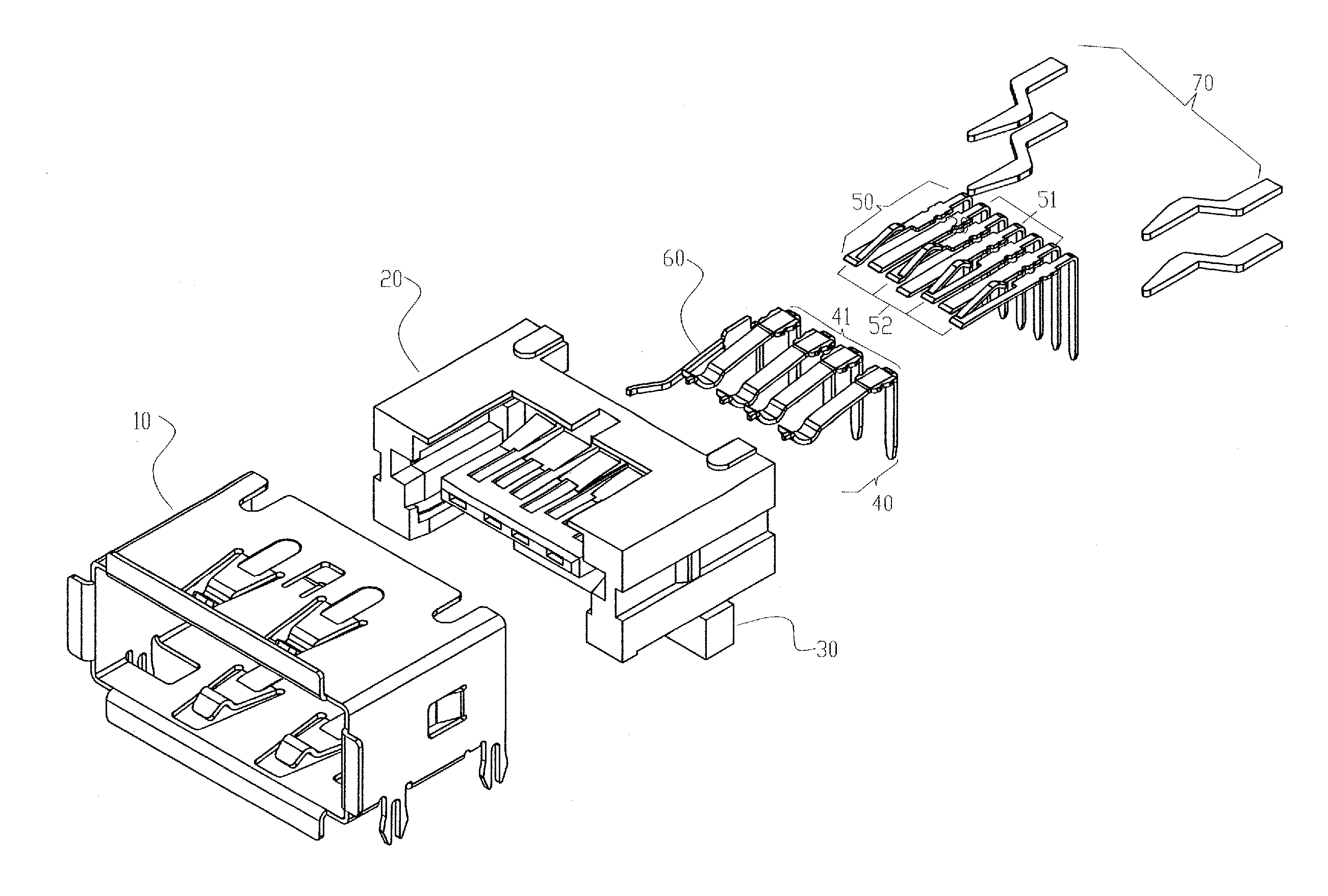
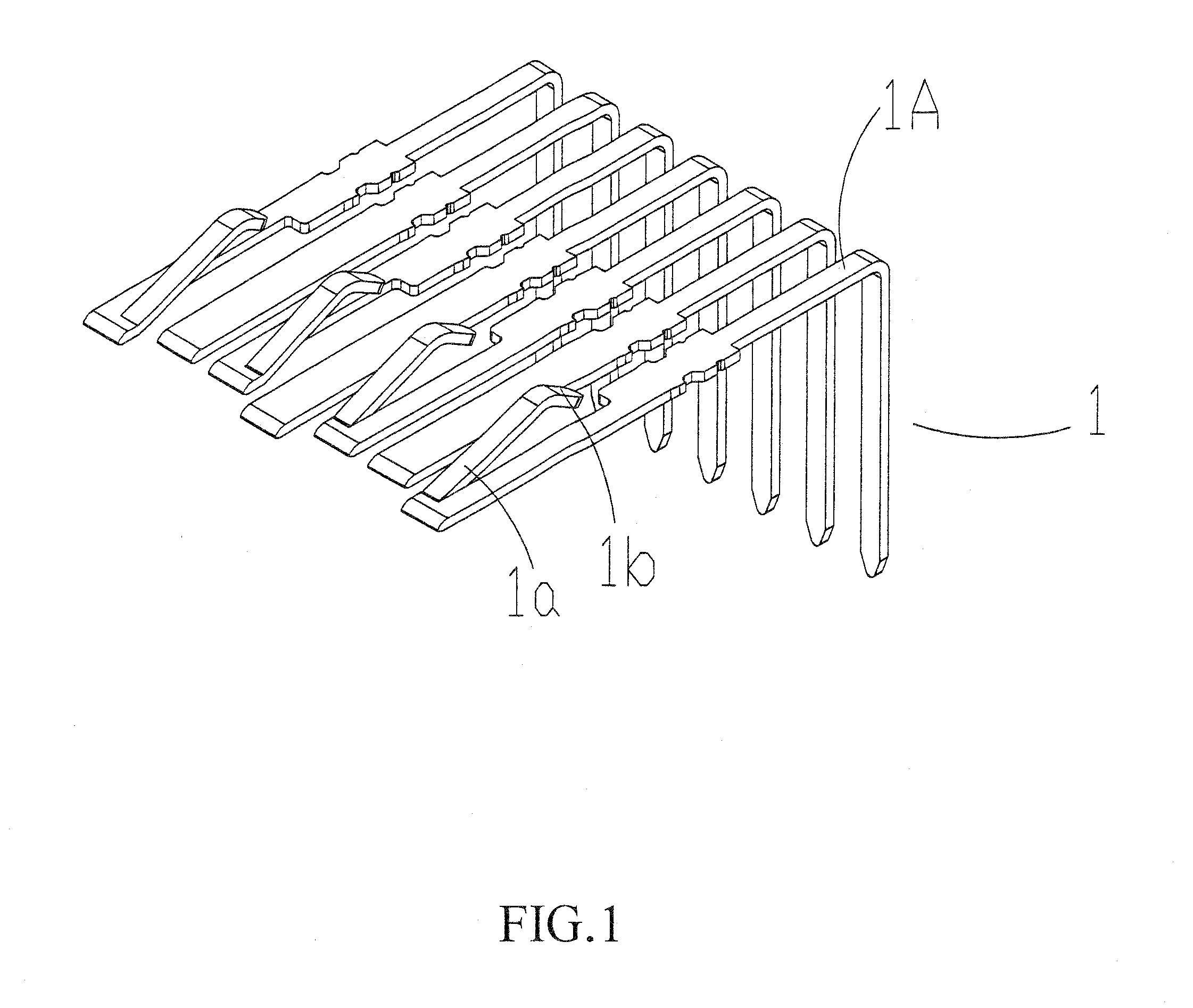
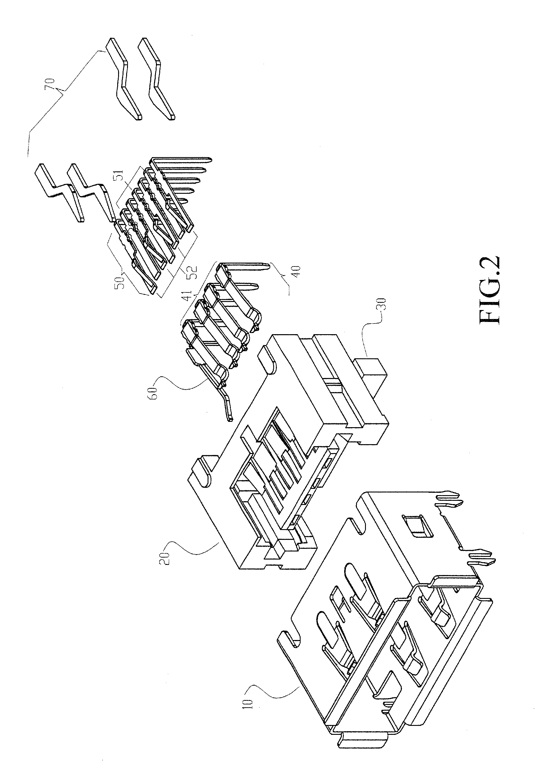
[0033]Referring to FIG. 1, the present invention discloses an improved terminal structure of connector, which comprises a group of terminals, generally designated at 1. The terminal group 1 comprises at least one terminal 1A that has a front end having a portion that is inclined to form an inclination section 1a that is partially separated from the terminal 1A. The inclination section 1a is further extended in a substantially horizontal direction to then form a bent section 1b. When the terminal gro...


PUM


Abstract

A terminal structure has a portion that is separated and bent. A projecting section is provided for realize common use. A connector port incorporating the terminal is also provided. The connector port includes a hollow shell receiving and retaining therein an insulation housing for receiving and positioning a plurality of terminals. Further, the insulation housing has at least one detection pin arranged at one side thereof. The detection pin is engageable with an external plug connector fit therein in order to prevent shorting caused by a shell of the plug contacting the terminals of the port at the time when the connectors mate each other. Further, the insulation housing includes a plurality of clamps, which functions to clamp and position an external plug connector so as to securely retain the plug that is fit into the socket and to realize stable engagement when the connector mate each other.

Description

CROSS-REFERENCE TO RELATED APPLICATION[0001]This is a non-provisional patent application claiming priority of provisional patent application Ser. No. 61 / 409,985 filed Nov. 4, 2010.TECHNICAL FIELD OF THE INVENTION[0002]The present invention generally relates to an improved terminal structure of connector and a connector port incorporating the terminal, in which the terminal structure has a portion that is separated and bent to realize common use.DESCRIPTION OF THE PRIOR ART[0003]Development and progress of science and technology makes telecommunication products getting widely and increasingly popular. Various electronic devices are allowed to connect to each other by means of transmission cables for data transmission. The electronic devices are thus provided with a connector port for receiving insertion of a plug attached to an end of a transmission cable. To effectively mount terminals on a tongue plate for improving utilization of internal space of a connector, a solution adopted i...

Claims


Application Information

Patent Timeline
Patent Type & Authority Patents(United States)
IPC IPC(8): H01R24/00
CPCH01R13/05H01R12/724H01R13/26H01R24/60H01R27/00
Inventor CHIANG, JUI-TU
Owner TAIWAN ELECTRONICS
Why Eureka
Try Eureka