
System and method for rejecting heat from equipment via endothermic isomerization

a technology of endothermic isomerization and heat sink, which is applied in the direction of indirect heat exchangers, hydrocarbon preparation catalysts, lighting and heating apparatus, etc., can solve the problems of difficult heat rejection, heat imparting into the skin of the aircraft, and equipment in vehicles that generate heat that must be dissipated or rejected

Active Publication Date: 2014-07-01
LOCKHEED MARTIN CORP
View PDF23 Cites 27 Cited by
  • Summary
  • Abstract
  • Description
  • Claims
  • Application Information

AI Technical Summary

Problems solved by technology

Equipment in vehicles, such as airborne vehicles, land-based vehicles, space-based vehicles, and other such mobile equipment often generate heat that must be dissipated or rejected.
In other implementations, however, rejecting heat is more difficult.
For example, air impacting onto a high-speed aircraft often imparts heat into the aircraft's skin due to friction, instead of removing heat from the skin.
If rejecting heat from such equipment is difficult or impossible, the equipment will continue to undesirably increase in temperature so long as heat is being generated within the equipment.
When the fuel is burned, the rejected heat leaves the equipment.
Problems, however, exist with such implementations.
Firstly, if sufficient heat is rejected into the fuel, the temperature of the fuel may increase to the point where the fuel thermally breaks down.
This situation can cause buildups of deposits within the equipment's fuel system, resulting in reduced equipment performance and / or undesired behavior.
Secondly, the fuel may come into contact with components, such as gaskets and electronics, of the equipment that have limited tolerance to high temperatures.

Method used


Image

  • System and method for rejecting heat from equipment via endothermic isomerization
  • System and method for rejecting heat from equipment via endothermic isomerization
  • System and method for rejecting heat from equipment via endothermic isomerization

Examples


Embodiment Construction

[0018]Illustrative embodiments of the invention are described below. In the interest of clarity, not all features of an actual implementation are described in this specification. It will of course be appreciated that in the development of any such actual embodiment, numerous implementation-specific decisions must be made to achieve the developer's specific goals, such as compliance with system-related and business-related constraints, which will vary from one implementation to another. Moreover, it will be appreciated that such a development effort might be complex and time-consuming but would nevertheless be a routine undertaking for those of ordinary skill in the art having the benefit of this disclosure.

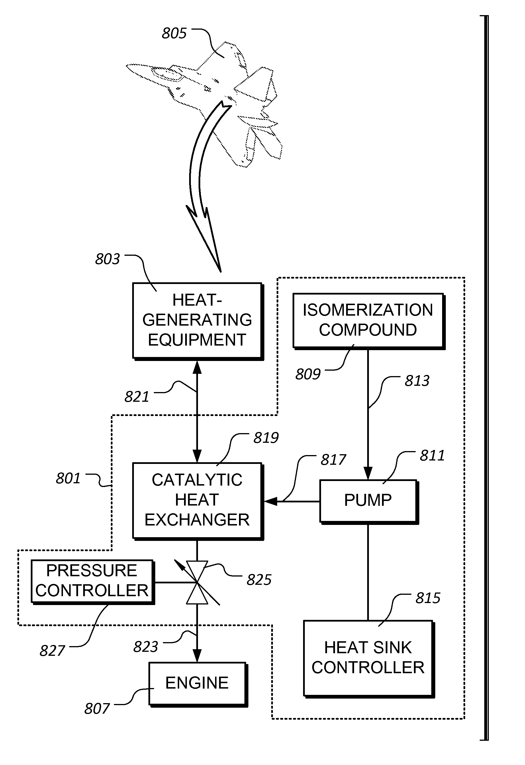
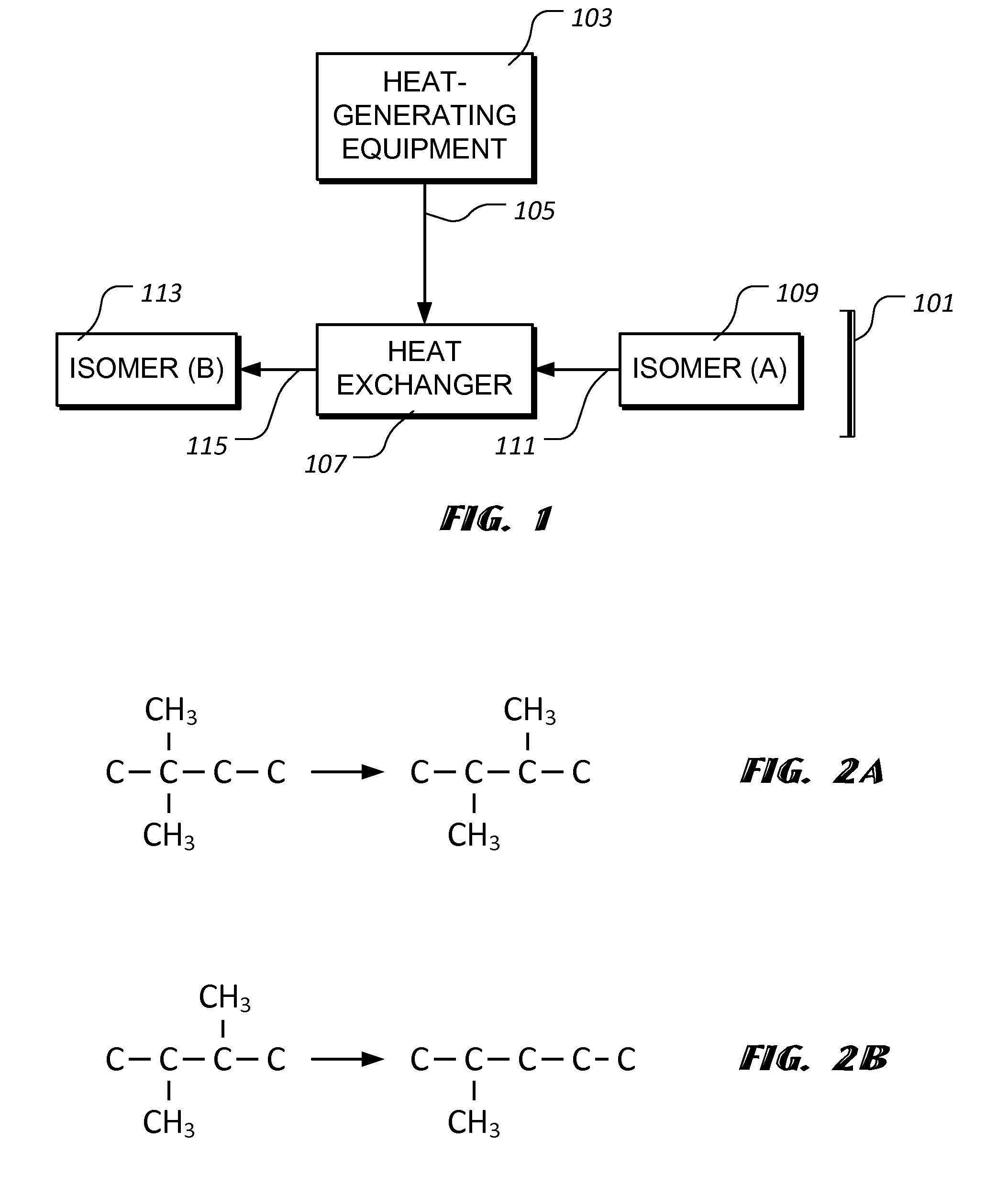
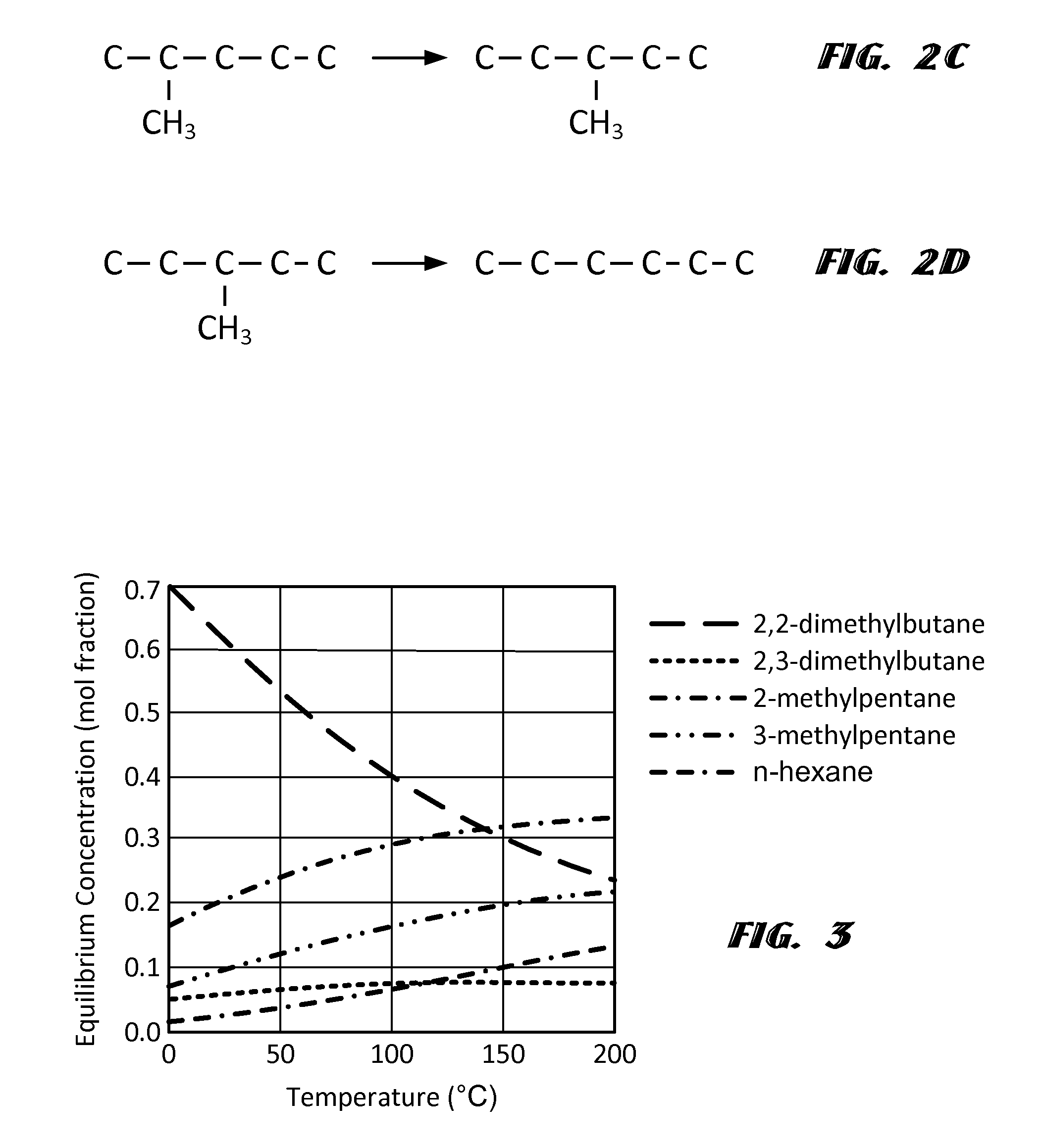
[0019]The present invention represents a system and method for rejecting heat from equipment via endothermic isomerization. FIG. 1 provides a graphical representation of an illustrative embodiment of a system 101 for rejecting heat from a heat-generating equipment 103. In the illu...


PUM


Abstract

A system for rejecting heat from equipment using endothermic isomerization. includes a heat exchanger configured to receive an elevated-temperature process fluid and an isomerization compound capable of endothermic isomerization. When the system is in operation, heat from the elevated temperature process fluid is transferred to the isomerization compound and the isomerization compound endothermically isomerizes to a higher energy state form. A vehicle includes an engine and a body. The body houses a catalytic heat exchanger having an output in fluid communication with the engine, a pump for urging an isomerization compound into the heat exchanger, and a heat sink controller for controlling the pump. A method for rejecting heat from equipment using endothermic isomerization includes providing a compound capable of endothermic isomerization and transferring heat from a process fluid to the compound, such that the compound endothermically isomerizes to a higher energy level isomer.

Description

BACKGROUND[0001]1. Field of the Invention[0002]The present invention relates to heat sinks. In particular, the present invention relates to heat sinks for mobile implementations, such as vehicles.[0003]2. Description of Related Art[0004]Equipment in vehicles, such as airborne vehicles, land-based vehicles, space-based vehicles, and other such mobile equipment often generate heat that must be dissipated or rejected. For example, heat produced by an automobile engine is rejected via coolant flowing through the automobile's radiator. In low-speed aircraft, heat is often rejected via the aircraft's skin to the air flowing over the skin. In other implementations, however, rejecting heat is more difficult. For example, air impacting onto a high-speed aircraft often imparts heat into the aircraft's skin due to friction, instead of removing heat from the skin. If rejecting heat from such equipment is difficult or impossible, the equipment will continue to undesirably increase in temperature...

Claims


Application Information

Patent Timeline
Patent Type & Authority Patents(United States)
IPC IPC(8): B01J19/00B01J8/00B01J8/02B64D33/08B64D37/34F02C7/12
CPCB64D37/34B01J8/0285B01J2208/00132B01J2208/065B64D13/00B64D33/08B64D2013/0614B64D2013/0633C07C5/2705C07C5/2721C07C2521/06C07C2527/126C07C2527/133F02C7/12F28D7/1607F28D21/00F28F13/003C07C9/16
Inventor NORTON, DANIEL G.PERRY, ROBERT J.ALLEN, EDWARD H.GLASER, PAUL B.
Owner LOCKHEED MARTIN CORP
Learn More