Sorting device

a sorting device and sorting technology, applied in the direction of conveyor parts, conveyors, packaging, etc., can solve the problems of limited risk and the risk of objects getting jammed in the slot, and achieve the effect of reducing the risk of objects getting jammed

Inactive Publication Date: 2014-07-08
VANDERLANDE IND
View PDF17 Cites 9 Cited by
  • Summary
  • Abstract
  • Description
  • Claims
  • Application Information

AI Technical Summary

Benefits of technology

[0016]In order to further reduce the risk of objects getting jammed in gaps formed between abutting front and rear edges of the adjacent load carrying platforms, it is preferable if adjacent load carrying platforms overlap at the location of the associated abutting front and rear edges, in which case adjacent load carrying platforms are arranged in line with each other, as described with reference to the preceding preferred embodiment.
[0017]From a practical point of view, said overlap can be realised in an advantageous manner if the abutting front and rear edges have a complementary stepped configuration, seen in vertical section parallel to the conveying direction and / or if the abutting front and rear edges have a parallel inclined configuration, seen in vertical section parallel to the conveying direction. An overlap realised in this way makes it possible in a relatively simple manner, in spite of the overlap, to remove a single load carrying platform from the train of load carrying platforms and replace it by another load carrying platform.

Problems solved by technology

The use of a through slot in a load carrying platform in principle involves the risk of objects getting jammed in the slot.
Tests have shown, however, that in practice this risk is limited and, in addition, can be further reduced by taking additional measures, for example providing brushes which extend within the slot, along which the connecting means can move.

Method used


Image

  • Sorting device
  • Sorting device
  • Sorting device

Examples


Embodiment Construction

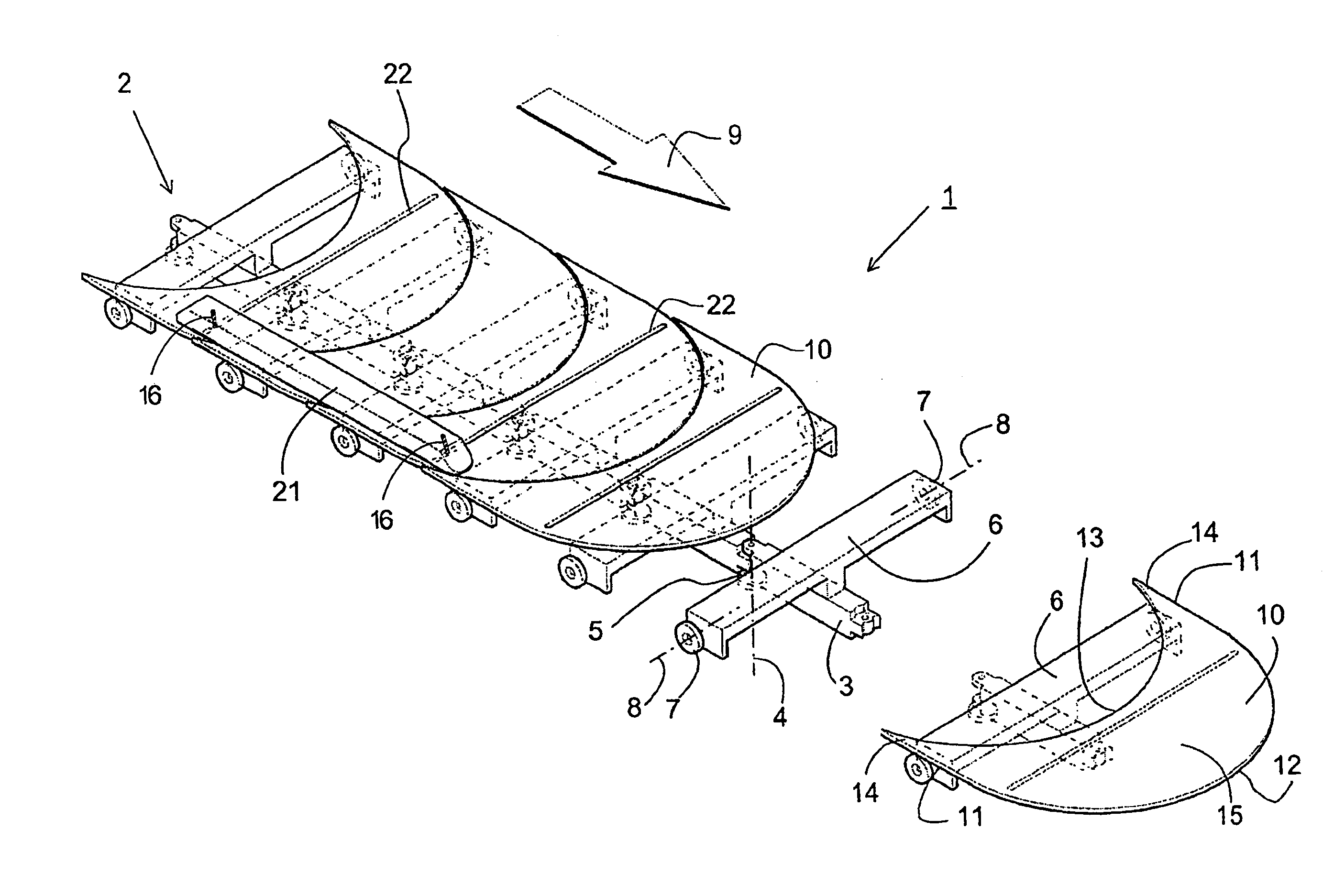
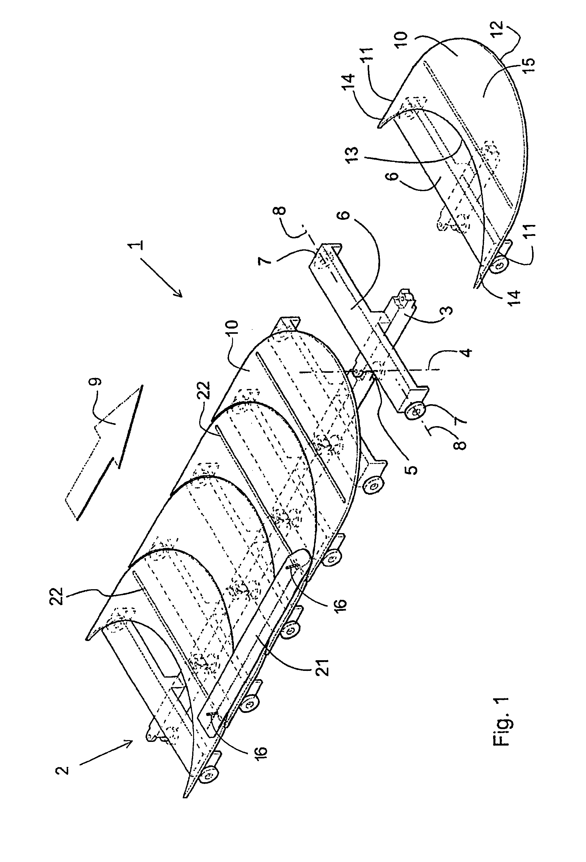
[0031]FIG. 1 shows part of a sorting device 1 according to a first preferred embodiment of the invention. The sorting device 1 comprises a chain 2. The chain 2 comprises links 3, which are pivotally connected about vertical pivot axles 4. A guide wheel 5 is provided for each link 3, the central axis of which guide wheel coincides with that of an associated pivot axles 4. The guide wheels 5 run in a U-shaped guide (not shown), which extends in an endless conveying path. Provided at the upper side of each link 3 is furthermore a transversely oriented supporting arm 6, with running wheels 7 mounted to two opposite ends thereof, the central axes of which running wheels are oriented transversely to the conveying direction 9 of the sorting device 1 and in line with each other. The running wheels 7 run on rails (not shown), which extend parallel to the conveying path defined by the U-shaped guides the guide wheels 5.

[0032]Furthermore, a load carrying platform 10 is provided for each link. ...


PUM


Abstract

A sorting device including successive load carrying platforms having a front edge and a rear edge for supporting products to be sorted on a supporting surface, a conveying mechanism conveying the load carrying platforms in a conveying direction along a conveying path, a sorting mechanism including plural pusher elements pushing a product to be sorted sideways off at least one supporting surface at a desired sorting location. The pusher elements each extend above at least one load carrying platform and are arranged for being jointly conveyed with the at least one load carrying platform in the conveying direction. A drive mechanism moves the at least one pusher element sideways at the desired sorting location. An arcuate shape of a front edge of a load carrying platform, as seen in top plan view, abuts an arcuate shape of a rear edge of a next load carrying platform.

Description

[0001]The present invention relates to a sorting device for sorting products, comprising successive load carrying platforms having a front edge and a rear edge for supporting products to be sorted on a supporting surface thereof, conveying means for conveying the load carrying platforms in a conveying direction along a conveying path, sorting means comprising a plurality of pusher elements for pushing a product to be sorted sideways off at least one supporting surface at a desired sorting location using at least one pusher element which pusher elements each extend above at least part of said at least one load carrying platform and which are arranged for being jointly conveyed with said at least one load carrying platform in the conveying direction, and drive means for moving said at least one pusher element sideways at a desired sorting location.BACKGROUND OF THE INVENTION[0002]In 2007, a sorting system called BAXORTER, in particular for automated luggage handling, was put on the ma...

Claims


Application Information

Patent Timeline
Patent Type & Authority Patents(United States)
IPC IPC(8): B65G47/46B65G17/00B65G17/06B65G21/16B65G47/84
CPCB65G47/844B65G17/005B65G17/066B65G21/16B65G2207/36
Inventor VAN DEN GOOR, JACOBUS MARIEVAN SCHAIJK, ERWIN HENDRIKUS PETRUS MARTINUS JOHANNESVERTOGEN, MARTINUS JOHANNES MARIAVISSERS, JOHANNES PETRUS MARIA
Owner VANDERLANDE IND
Why Eureka
Try Eureka