Helical strakes with molded in stand-offs

a technology of helical strakes and stand-offs, which is applied in the direction of foils, pipe laying and repair, and valve movement reduction. it can solve the problems of cathodic protection systems being compromised, oil and gas exploration and production is managing significant ocean currents, and the suspension of drilling

Active Publication Date: 2014-07-08
VIV SOLUTIONS
View PDF21 Cites 20 Cited by
  • Summary
  • Abstract
  • Description
  • Claims
  • Application Information

AI Technical Summary

Problems solved by technology

A difficult obstacle associated with the exploration and production of oil and gas is management of significant ocean currents.
VIV can cause substantial fatigue damage to the tubular or cause suspension of drilling due to increased deflections.
This causes a problem with many cathodic protection systems, which require the circulation of fluid adjacent to the tubular in order for the cathodic protection systems to function properly.
Since the helical strake bodies are typically wrapped sufficiently tight against the tubular surface to restrict slipping on a vertical tubular, the cathodic protection systems may be compromised.
In addition, the presence of helical strake body adjacent to the tubular surface can also produce unwanted thermal insulation.

Method used


Image

  • Helical strakes with molded in stand-offs
  • Helical strakes with molded in stand-offs
  • Helical strakes with molded in stand-offs

Examples


Embodiment Construction

[0024]In this section we shall explain several preferred embodiments with reference to the appended drawings. Whenever the shapes, relative positions and other aspects of the parts described in the embodiments are not clearly defined, the scope of the embodiments is not limited only to the parts shown, which are meant merely for the purpose of illustration. Also, while numerous details are set forth, it is understood that some embodiments may be practiced without these details. In other instances, well-known structures and techniques have not been shown in detail so as not to obscure the understanding of this description.

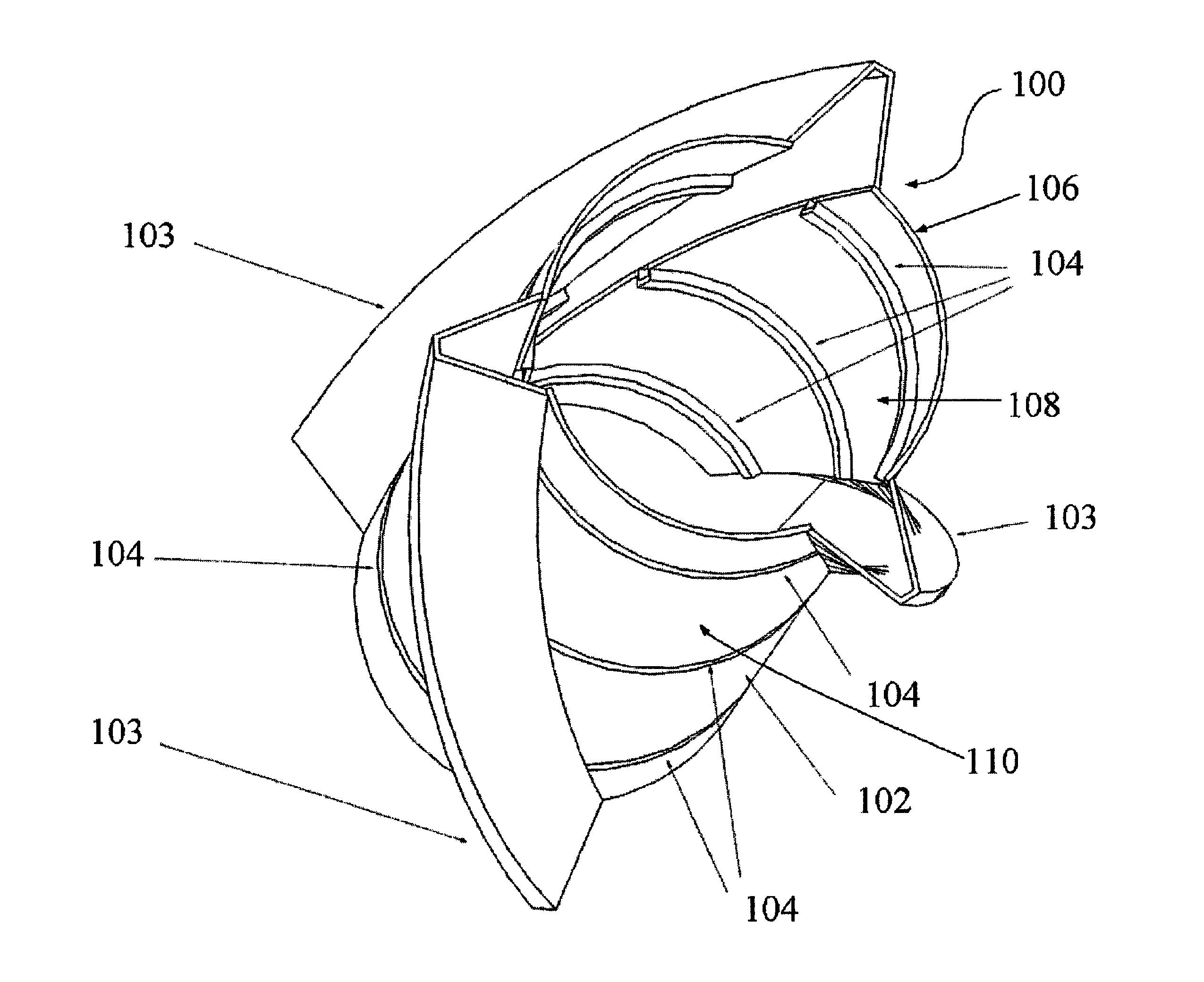
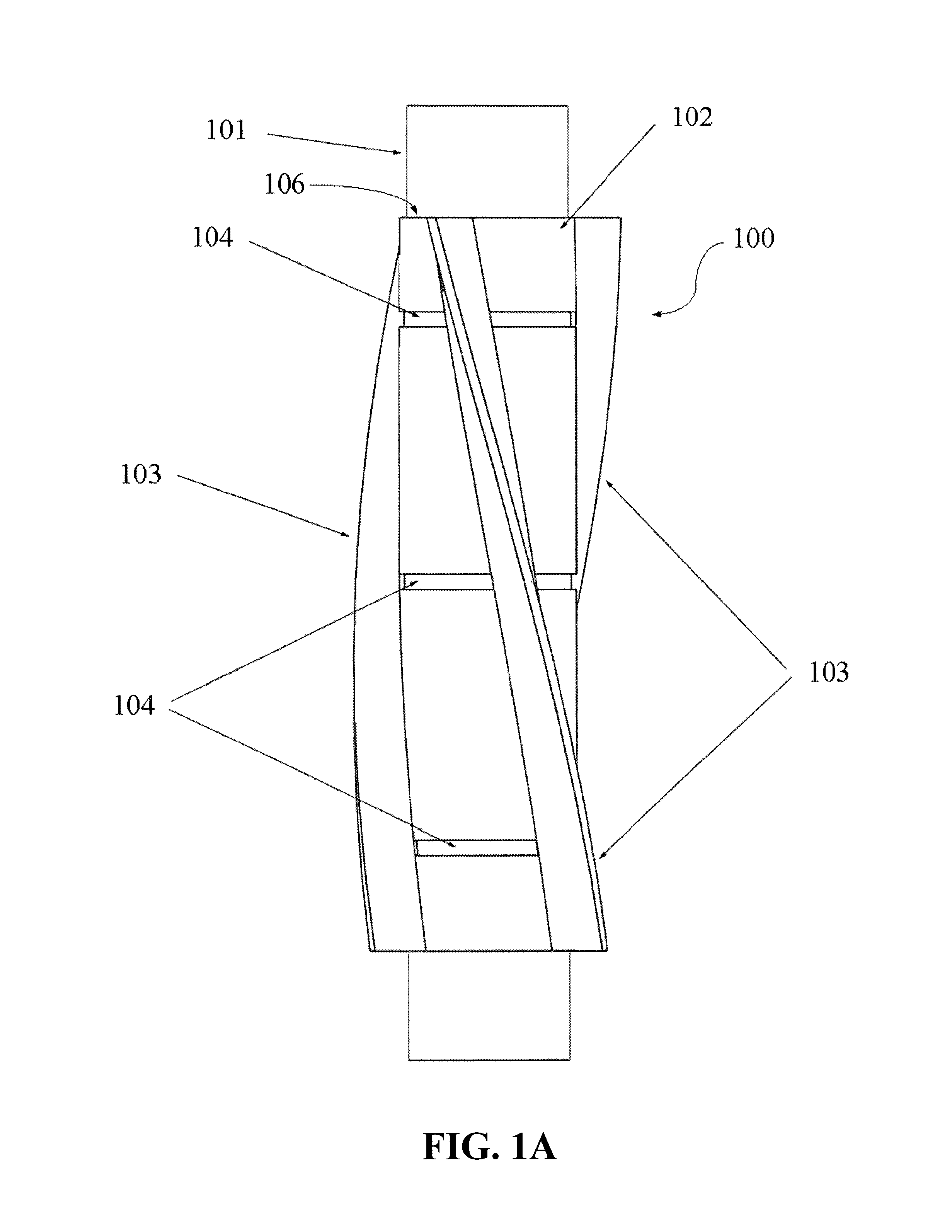
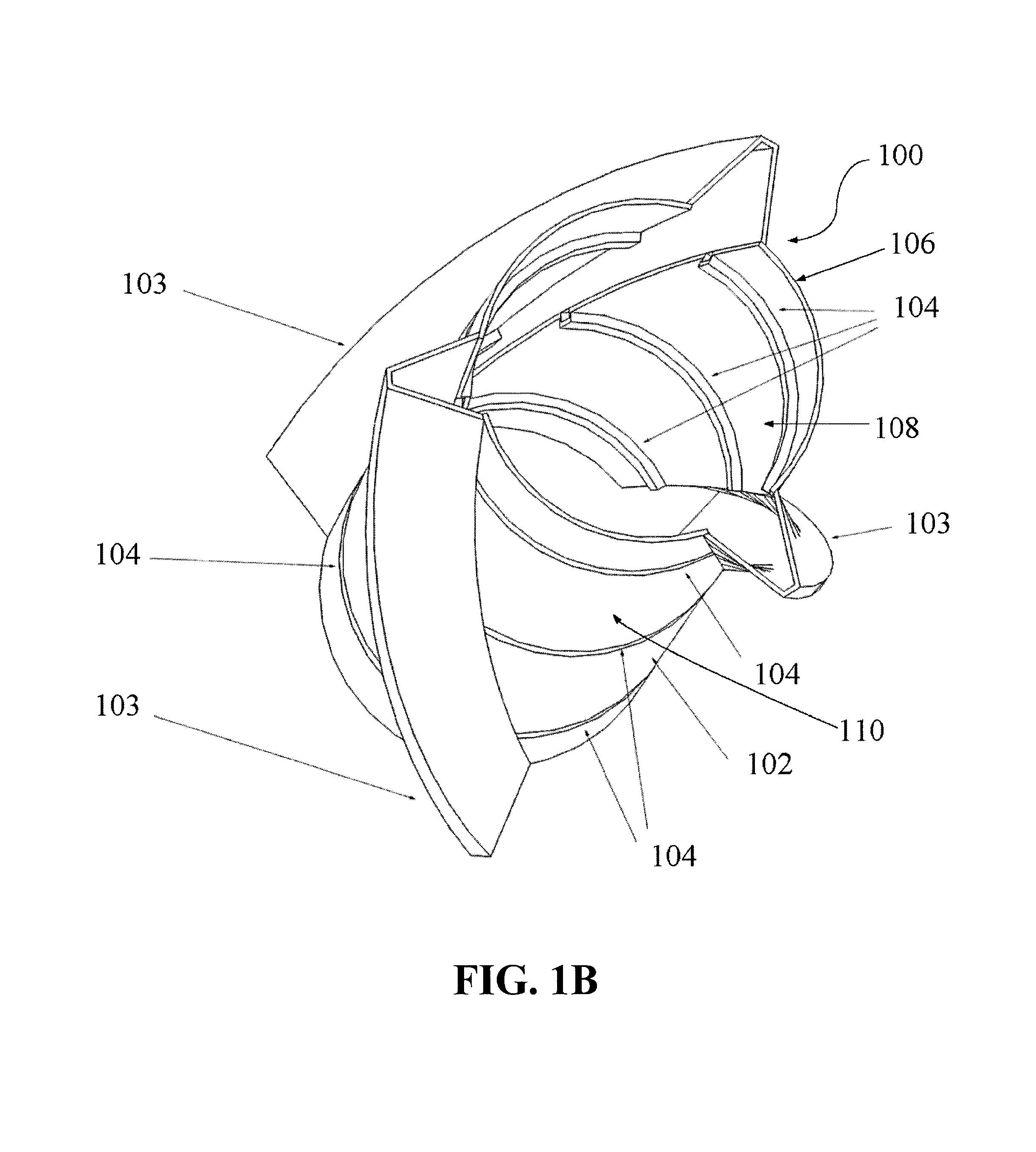
[0025]Referring now to an example embodiment of the invention in more detail, FIG. 1A presents VIV suppression device 100 on tubular 101. In one embodiment, VIV suppression device 100 may be a helical strake including body 102, fins 103 and stand-offs 104. Body 102 may be formed by a substantially cylindrical wall 106 dimensioned to encircle tubular 101. In some emb...


PUM


Abstract

A vortex-induced vibration (VIV) suppression device including a body having a wall dimensioned to at least partly envelope a tubular member in an interior area of the body. The device further including a fin protruding outward from an exterior surface of the wall and a stand-off member positioned along an interior surface of the wall. The stand-off member dimensioned to space the body away from the tubular member and having a protruding portion formed by the interior surface of the wall and an indention portion formed by the exterior surface of the wall.

Description

CROSS-REFERENCE TO RELATED APPLICATION[0001]The application is a non-provisional application of co-pending U.S. Patent Application No. 61 / 580,461, filed Dec. 27, 2011 and incorporated herein by reference.FIELD[0002]Vortex-induced vibration (VIV) suppression devices having stand-offs to space the device from an underlying tubular. Other embodiments are also described herein.BACKGROUND[0003]A difficult obstacle associated with the exploration and production of oil and gas is management of significant ocean currents. These currents can produce vortex-induced vibration (VIV) and / or large deflections of tubulars associated with drilling and production. VIV can cause substantial fatigue damage to the tubular or cause suspension of drilling due to increased deflections.[0004]Helical strakes can be installed over the tubular to mitigate VIV. Helical strakes reduce the correlation of vortex shedding and thereby reduce the synchronization of vortex shedding forces required to produce large vi...

Claims


Application Information

Patent Timeline
Patent Type & Authority Patents(United States)
IPC IPC(8): F15D1/10
CPCF15D1/10B63B39/06F16L1/123E21B17/01
Inventor ALLEN, DONALD WAYNEDEHNE, JULIE ANNWEST, WILLIAM ANDREWDEHNE, TROY WILLIAM
Owner VIV SOLUTIONS
Why Eureka
Try Eureka