
Battery management system, method of removing polarization voltage of battery, and estimating state of charge of battery

a battery management system and battery technology, applied in the field of battery management system, can solve the problems of deteriorating the power quality of all power systems, not easy to control the amount of renewable energy generation, and the inability to accurately estimate the voltage of the battery, so as to achieve the effect of quick removal and accurate estimation of the soc of the battery

Inactive Publication Date: 2014-07-08
SAMSUNG SDI CO LTD
View PDF17 Cites 12 Cited by
  • Summary
  • Abstract
  • Description
  • Claims
  • Application Information

AI Technical Summary

Benefits of technology

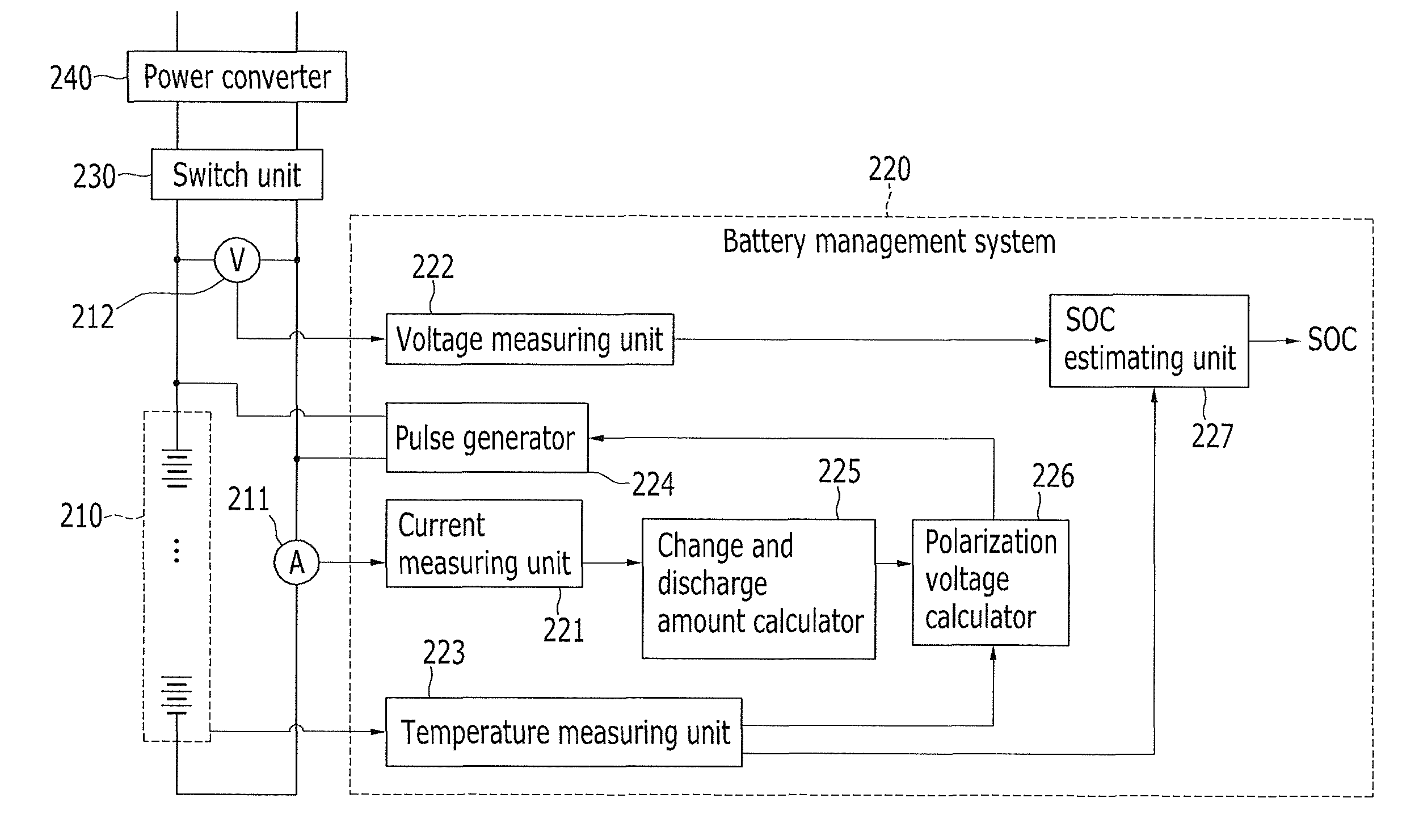
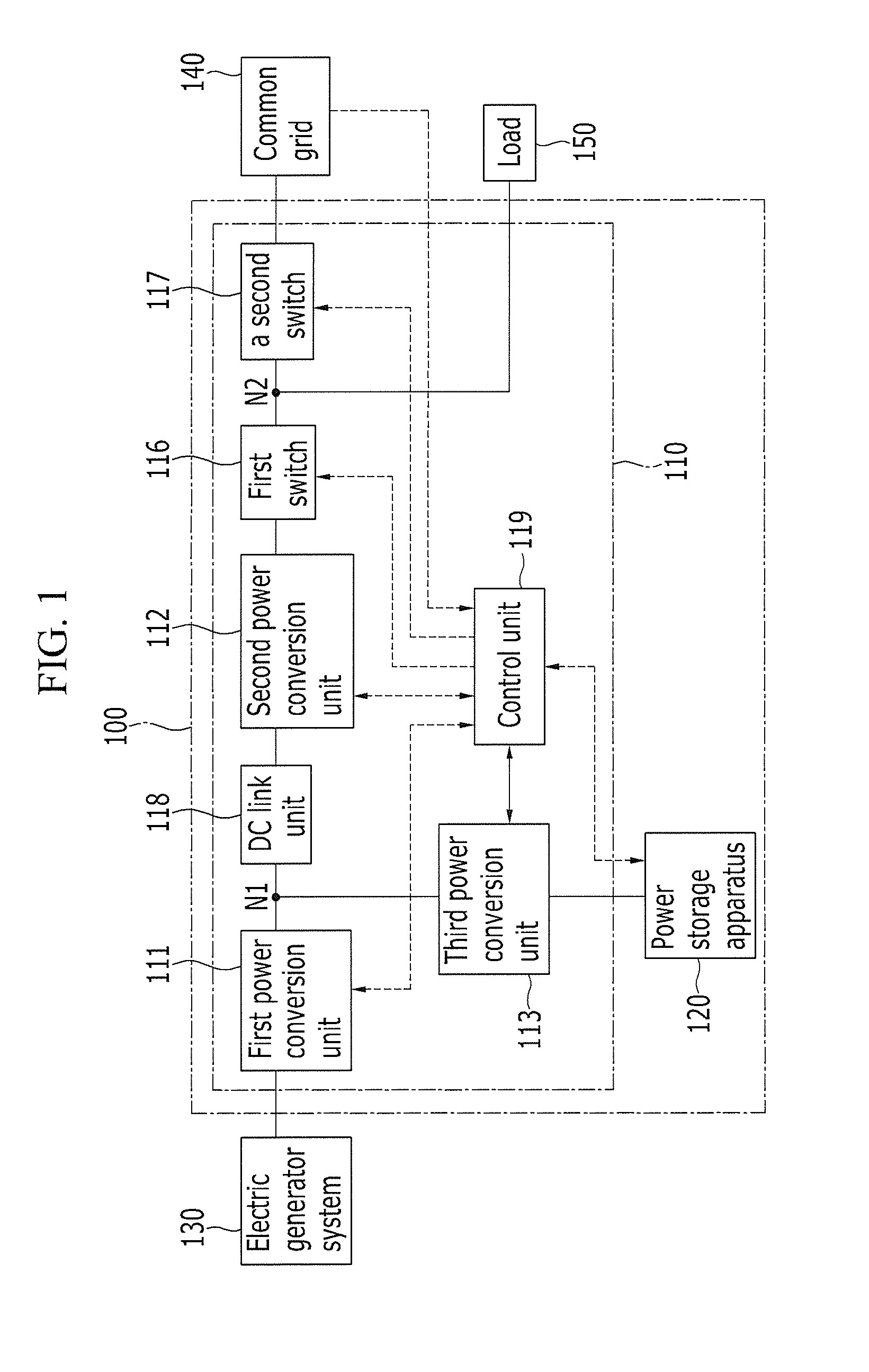
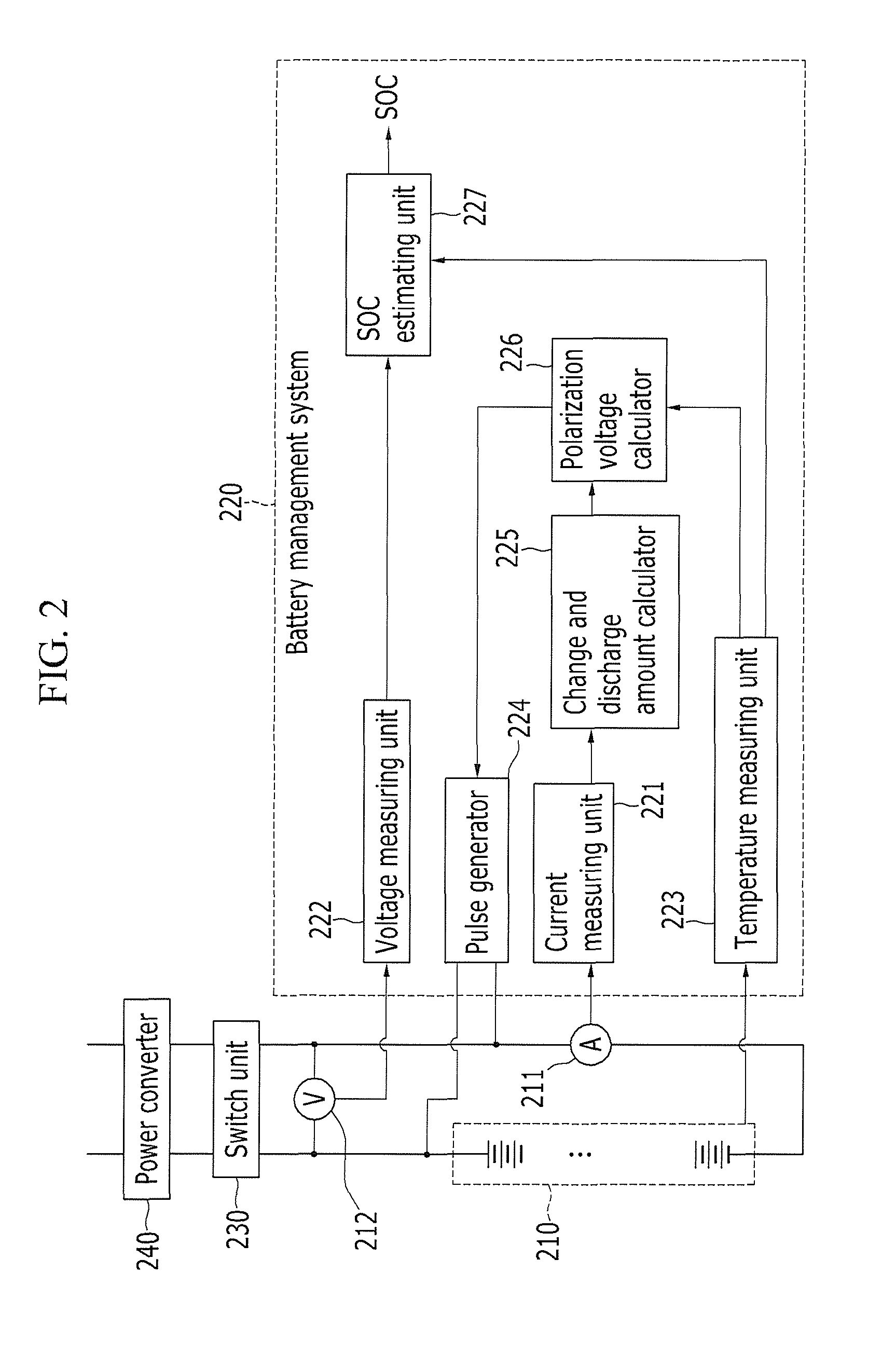
[0013]Aspects of embodiments of the present invention are directed toward a battery management system for quickly removing a polarization voltage generated according to charge and discharge of a battery to more accurately estimate a charge state of the battery, a method of removing a battery polarization voltage, and a method of estimating a battery charge state.
[0032]The polarization voltage generated according to the charge and discharge of the battery may be quickly removed, and the SOC of the battery may be more accurately estimated.

Problems solved by technology

It is not easy to control the amount of generation of renewable energy.
If the supply quantity of renewable energy does not coincide with the demand quantity of renewable energy in real time, abnormalities are generated in voltage and frequency, thereby possibly deteriorating the power quality of all of the power systems.
The SOC of the battery may be estimated by measuring the voltage, however the voltage of the battery may not be accurately measured because of the polarization voltage that is generated in the process of charge and discharge.
The SOC of the battery may be estimated by measuring the current, however there is a limitation in that an initial SOC of the battery must be recognized for the SOC estimation using the current measuring.

Method used


Image

  • Battery management system, method of removing polarization voltage of battery, and estimating state of charge of battery
  • Battery management system, method of removing polarization voltage of battery, and estimating state of charge of battery
  • Battery management system, method of removing polarization voltage of battery, and estimating state of charge of battery

Examples


Embodiment Construction

[0042]Hereinafter, some exemplary embodiments of the present invention are described in detail with reference to the accompanying drawings in order for those skilled in the art to be able to readily practice the exemplary embodiments.

[0043]Furthermore, in some exemplary embodiments, constituent elements having the same construction are assigned the same reference numerals and are described in connection with an initial exemplary embodiment as a representative example. In the remaining exemplary embodiments, only constituent elements different from those of the initial exemplary embodiment are described.

[0044]In order to clarify description of the present invention, parts not related to the description are omitted, and the same reference numbers are used throughout the drawings to refer to the same or like parts.

[0045]Throughout this specification and the claims that follow, when it is described that an element is “coupled” to another element, the element may be “directly coupled” to...


PUM

PropertyMeasurementUnit
charge currentaaaaaaaaaa
discharge currentaaaaaaaaaa
polarization voltage calculatoraaaaaaaaaa

Abstract

A battery management system according to an exemplary embodiment of the present invention includes: a current measuring unit for sampling a charge current and a discharge current of a battery; a charge and discharge amount calculator for calculating a charge and discharge amount corresponding to a difference between the sampled charge current and the sampled discharge current; a polarization voltage calculator for calculating a polarization voltage corresponding to the charge and discharge amount and a temperature of the battery; and a pulse generator for applying a polarization voltage reset pulse for the battery to remove the polarization voltage.

Description

CROSS-REFERENCE TO RELATED APPLICATION[0001]This application claims priority to and the benefit of Korean Patent Application No. 10-2011-0011634, filed in the Korean Intellectual Property Office on Feb. 9, 2011, the entire content of which is incorporated herein by reference.BACKGROUND[0002]1. Field[0003]The following description relates to a battery management system, a method of removing a battery polarization voltage, and a method of estimating a battery charge state.[0004]2. Description of Related Art[0005]Recently, the European Union has decided upon a plan to expand the percentage of renewable energy, from among all electric power sources, up to 20% by the year 2020 and 50% by the year 2050. The United States of America is also planning to carry out Renewable Portfolio Standards (RPS). In a situation where renewable energy increases from less than 5% in today's energy use to be up to 30 to 40% in the future, power systems should be prepared for these new changes.[0006]It is no...

Claims


Application Information

Patent Timeline
Patent Type & Authority Patents(United States)
IPC IPC(8): H01M10/44H01M10/46H02J7/00
CPCH02J7/00H02J3/32H02J3/382H02J3/385H02J3/386H02J2007/005Y02E10/58Y02E10/763Y02E70/30H02J7/0048H02J2300/28H02J2300/20H02J2300/26H02J3/381Y02E10/56Y02E10/76G01R31/36G01R19/165
Inventor CHOI, LOO-NEYSEO, KI-HOMURAKAMI, YUSAI
Owner SAMSUNG SDI CO LTD
Learn More