On-vehicle acoustic device and method of assembling the same

a technology for acoustic devices and vehicles, which is applied in the direction of electrical equipment casings/cabinets/drawers, manufacturing tools, transportation and packaging, etc., can solve the problems of limited improvement of sound quality in the car cabin, difficult to mount a woofer having a large diameter, and hardly possible to mount the speaker on the ceiling part, etc., to achieve the effect of improving sound quality and increasing the cabin

Active Publication Date: 2014-07-15
ALPINE ELECTRONICS INC
View PDF13 Cites 5 Cited by
  • Summary
  • Abstract
  • Description
  • Claims
  • Application Information

AI Technical Summary

Benefits of technology

[0016]In the on-vehicle acoustic device of the present invention, since the central part of the speaker is fixed to the reinforcing material of the ceiling part, the speaker can be firmly fixed to the ceiling part. The opening part having an inner diameter smaller than the diameter of the frame of the speaker is formed in the ceiling lining provided at the ceiling part, and the external peripheral part of the frame is pressed against the ceiling lining at the peripheral edge part of the opening part. Therefore, the ceiling lining can be used as a baffle wall, and sound pressure of a space between the top plate and the ceiling lining can be prevented from leaking into the interior of the car cabin, so that the sound inside the car cabin becomes better. Further, even when a large woofer is mounted, a sufficient space can be secured.
[0018]A gap between the frame and the ceiling lining is less likely to be formed by providing the frame interposing material, whereby blocking effect between a space between the ceiling lining and the top plate, and the car cabin can be increased.
[0021]The fixing screw can be screwed to the reinforcing material without slack by providing the central interposing material or the external peripheral interposing material. Further, direct action of vibration of the speaker on the reinforcing material or the top plate can be prevented.
[0028]The method of assembling an on-vehicle acoustic device of the present invention enables the speaker to be easily mounted from the inside of the car cabin without the necessity of removing the ceiling lining of the ceiling part or disassembling a car body.
[0035]The opening part having an internal diameter smaller than the diameter of the frame of the speaker is formed in the ceiling lining, and the external peripheral part of the frame is pressed against the ceiling lining at the peripheral edge part of the opening part, whereby a gap is less likely to be formed between the frame and the ceiling lining. Further, blocking effect between a space between the ceiling lining and a top plate, and the car cabin is increased by using the ceiling lining as a baffle wall, whereby the sound quality can be improved.
[0036]Further, the method of assembling the on-vehicle acoustic device of the present invention enables mounting of the speaker from the inside of the car cabin without removing the ceiling lining or disassembling the ceiling part.

Problems solved by technology

Therefore, there is limitation of improvement of sound quality in a car cabin.
Further, since the size of the speaker disposed at the rear tray or the car door is limited, it is difficult to mount a woofer having a large diameter, for example.
Therefore, it is difficult, with such a mounting structure in the related art, to mount the speaker on a ceiling part to which a relatively soft interior lining is provided.
However, since JP 6-62694 Y has the structure in which the fixing angle is fixed to an inner side of the hard plate material, and the fixing screw provided at the central part of the speaker is screwed to the fixing angle, it is hardly possible to mount the speaker on the ceiling part with the mounting structure disclosed in JP 6-62694 Y.

Method used


Image

  • On-vehicle acoustic device and method of assembling the same
  • On-vehicle acoustic device and method of assembling the same
  • On-vehicle acoustic device and method of assembling the same

Examples


first embodiment

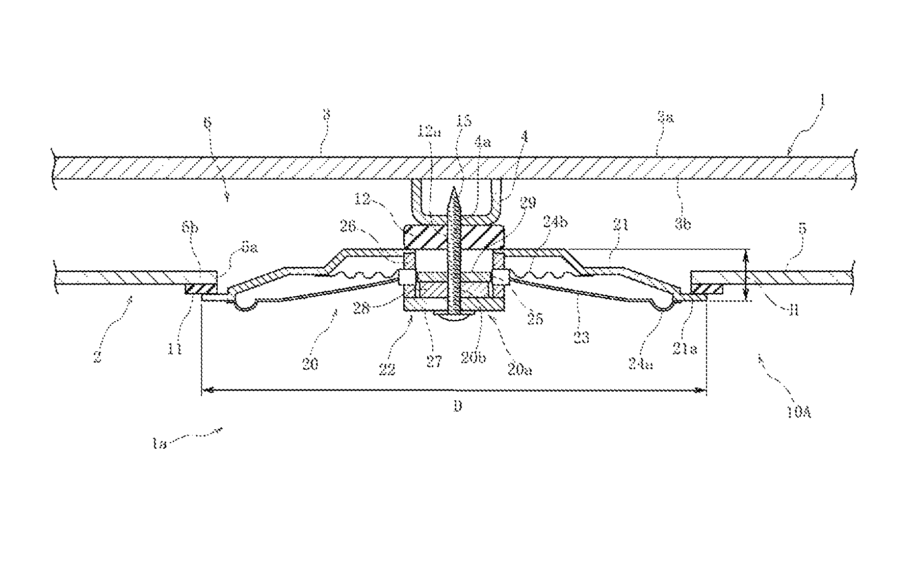
[0043]An on-vehicle acoustic device 10A of a first embodiment shown in FIG. 1 is provided to a ceiling part 2 of a car 1.

[0044]The car 1 is, for example, a minivan type automobile shown in FIG. 6. A top plate 3 made of a metal plate shown in FIG. 1 is provided to the ceiling part 2 of the car. An external surface 3a of the top plate 3 is an exterior surface of the car 1. A reinforcing material, also referred to as a reinforcing brace 4 is fixed to an internal surface 3b of the top plate 3. The reinforcing material 4 is a reinforcing frame or brace formed of steel channel material, is disposed so as to cross the ceiling part 2 of the car in the right-left direction as shown in FIG. 6, and is fixed to the top plate 3 by means of welding or the like.

[0045]As shown in FIG. 1, a ceiling lining 5 is provided closer to an inside of a car cabin 1a than the top plate 3 and the reinforcing material 4. The ceiling lining 5 is formed of synthetic leather which is softer than steel material but ...

second embodiment

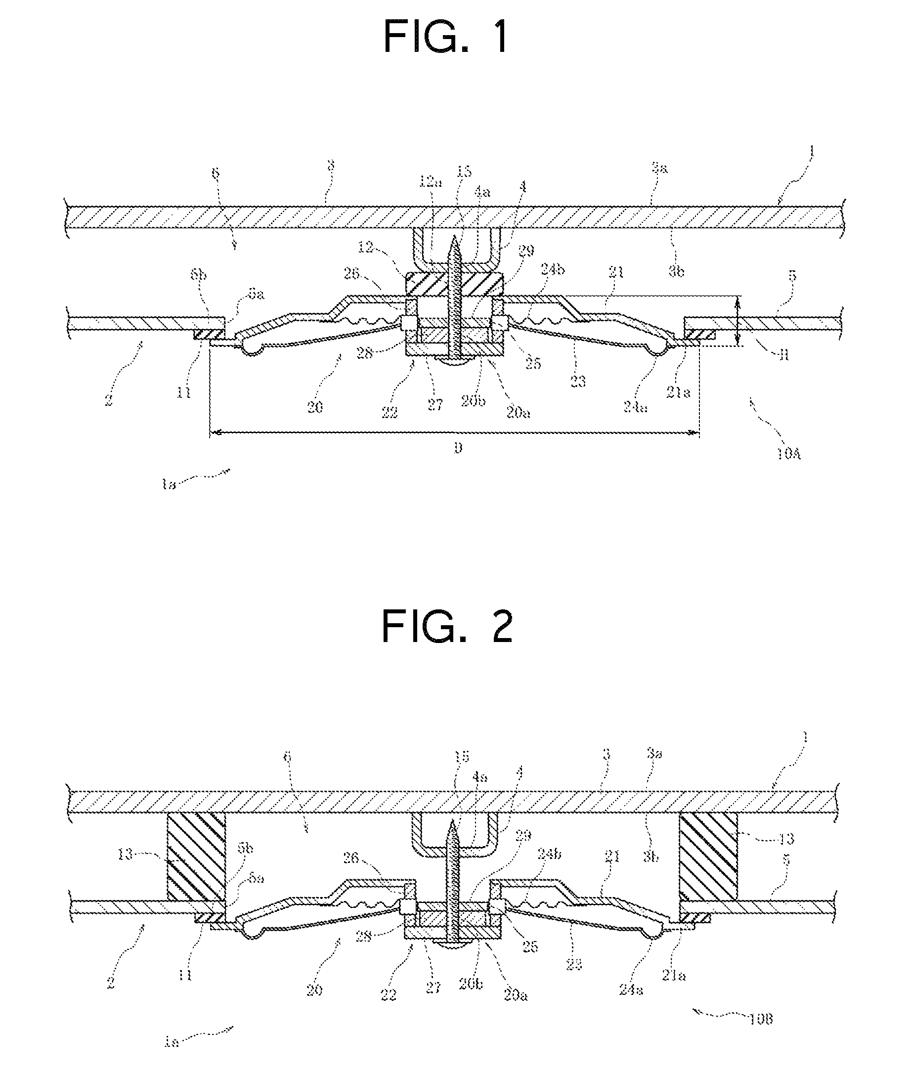
[0062]In the on-vehicle acoustic device 10B of a second embodiment shown in FIG. 2, the central interposing material 12 shown in FIG. 1 is not used, and instead, a plurality of external peripheral interposing materials 13 is used. The external peripheral interposing materials 13 are formed of the same elastic material as the central interposing material 12.

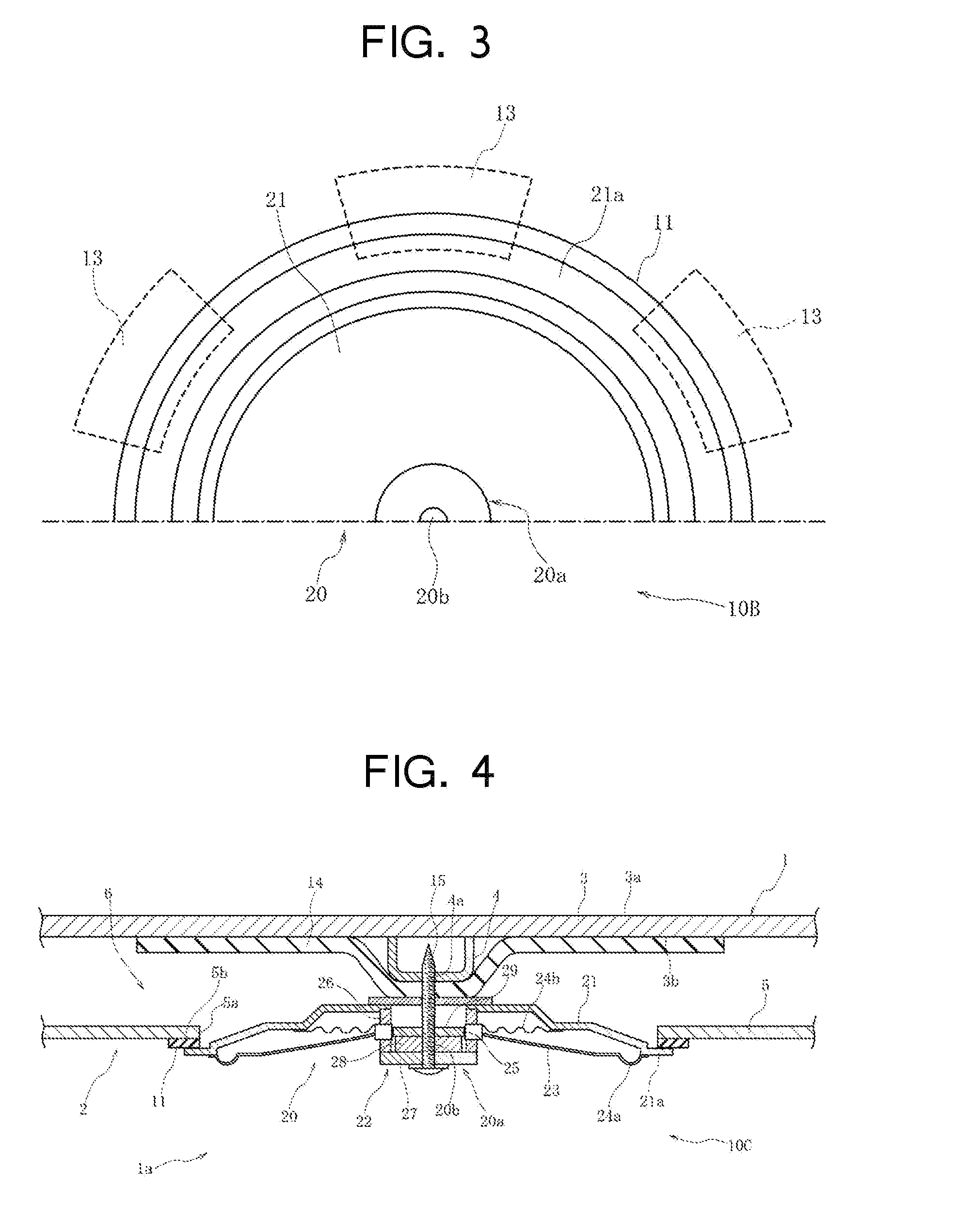
[0063]The external peripheral interposing materials 13 are interposed between a top plate 3 or a reinforcing material 4, and a ceiling lining 5 at a peripheral edge part 5b of an opening part 5a. As shown in FIG. 3, the several external peripheral interposing materials 13 are disposed at certain angle intervals along the peripheral edge part 5b of the opening part 5a.

[0064]It is desirable to fix each of the external peripheral interposing materials 13 and an internal surface 3b of the top plate 3 by an adhesive at a process after the opening part 5a is formed in the ceiling lining 5 and before a speaker 20 is disposed. Further, i...

third embodiment

[0066]The on-vehicle acoustic device 10C of a third embodiment shown in FIG. 4 includes a sound absorbent material 14 disposed at an internal surface 3b of a top plate 3. The sound absorbent material 14 functions as damping material and is formed of an elastic material such as synthetic rubber or foamed resin material.

[0067]The sound absorbent material 14 is larger than a speaker 20 in size and is disposed so as to cover the internal surface 3b of the top plate 3 and a reinforcing material 4. Further, at least a part of the sound absorbent material 14 is fixed to the top plate 3 by an adhesive or the like.

[0068]When the speaker 20 is mounted, a part of the sound absorbent material 14 is sandwiched between a central part 20a of the speaker 20 and the reinforcing material 4, and fixed between the central part 20a and the reinforcing material 4 by tightening force of a fixing screw 15. An effect of suppressing direct action of the vibration of the speaker 20 on the reinforcing material...


PUM

PropertyMeasurementUnit
heightaaaaaaaaaa
diameteraaaaaaaaaa
heightaaaaaaaaaa

Abstract

An opening is formed in a ceiling lining of a vehicle cabin part. The diameter of the opening in the ceiling lining is smaller than a diameter of a speaker, which has a frame. The speaker is disposed at the opening, and a fixing screw is inserted into a fixing aperture formed in a central part of the speaker. A fixing screw is screwed to a screw hole formed in a reinforcing brace positioned at an inner side of a top plate proximate the ceiling of the vehicle. A central part of the speaker is fixed to the reinforcing brace while a circumferential periphery of the frame is pressed against a peripheral edge of the opening in the ceiling lining via a frame interposing material.

Description

[0001]This application claims the benefit of Japanese Patent Application No. 2011-241133, filed on Nov. 2, 2011, and which is incorporated by reference herein in its entirety.BACKGROUND[0002]1. Field of the Invention[0003]The present invention relates to an on-vehicle acoustic device in which a speaker is mounted on a ceiling part of a car cabin of a car and a method of assembling the same.[0004]2. Description of the Related Art[0005]As an on-vehicle acoustic device in the related art, JP 5-35499 Y (CD-ROM) and JP 7-42288 Y (CD-ROM) disclose an on-vehicle acoustic device in which a speaker is mounted on a rear tray of a car.[0006]Each of these on-vehicle acoustic devices has an opening part formed in the rear tray of the car and a bracket mounted on a steel plate of the car positioned at an inward part of the rear tray. A central part of the speaker is inserted into the opening part, and an external peripheral part of a fame of the speaker is disposed at a periphery of the opening p...

Claims


Application Information

Patent Timeline
Patent Type & Authority Patents(United States)
IPC IPC(8): H04R1/02B60R11/02B60R11/00
CPCY10T29/49826B60R2011/0028B60R11/0223
Inventor ITO, RYOIMAI, MASAMIKANARI, TAKASHIANZAI, MASAMITADA, ARATA
Owner ALPINE ELECTRONICS INC
Why Eureka
Try Eureka