
Firearm trigger pull training system and methods

a training system and trigger technology, applied in the field of firearms, can solve the problems of inability to monitor the actual trigger movement in two dimensions, the inability to correlate the trigger pull path to the actual barrel displacement, and the inability to accurately fire the sho

Inactive Publication Date: 2014-07-15
TRIGGERMASTER LLC
View PDF19 Cites 56 Cited by
  • Summary
  • Abstract
  • Description
  • Claims
  • Application Information

AI Technical Summary

Benefits of technology

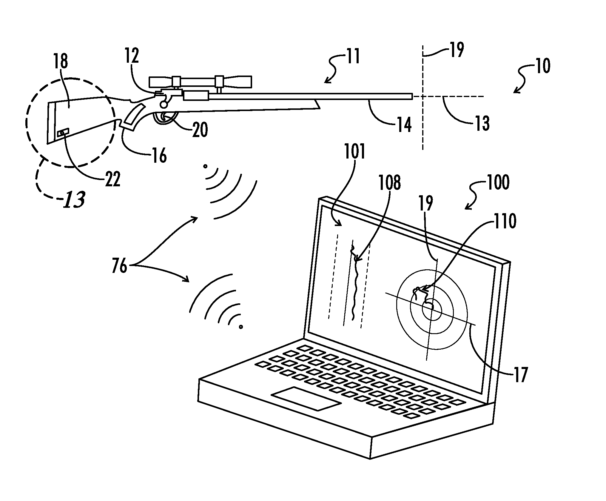
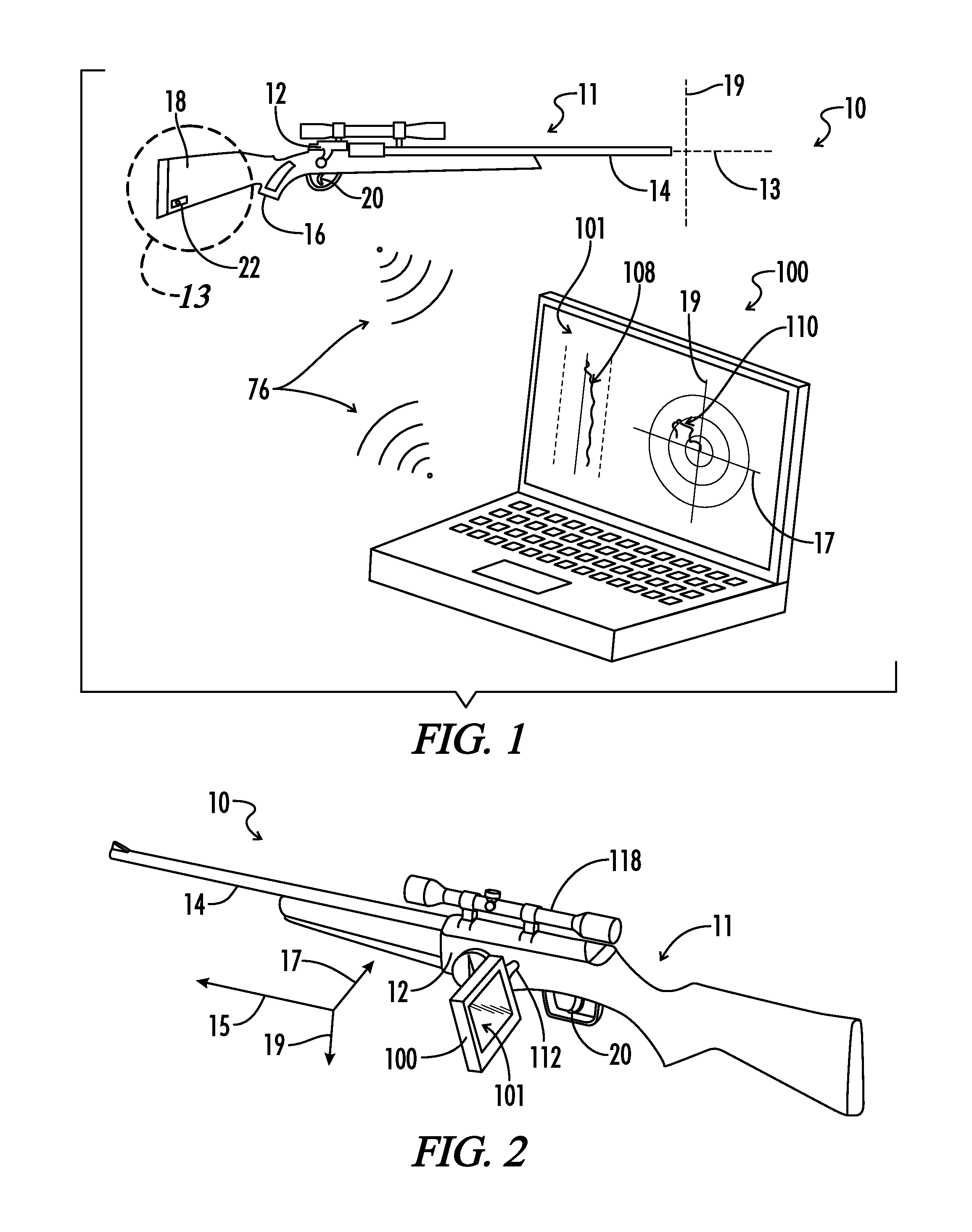
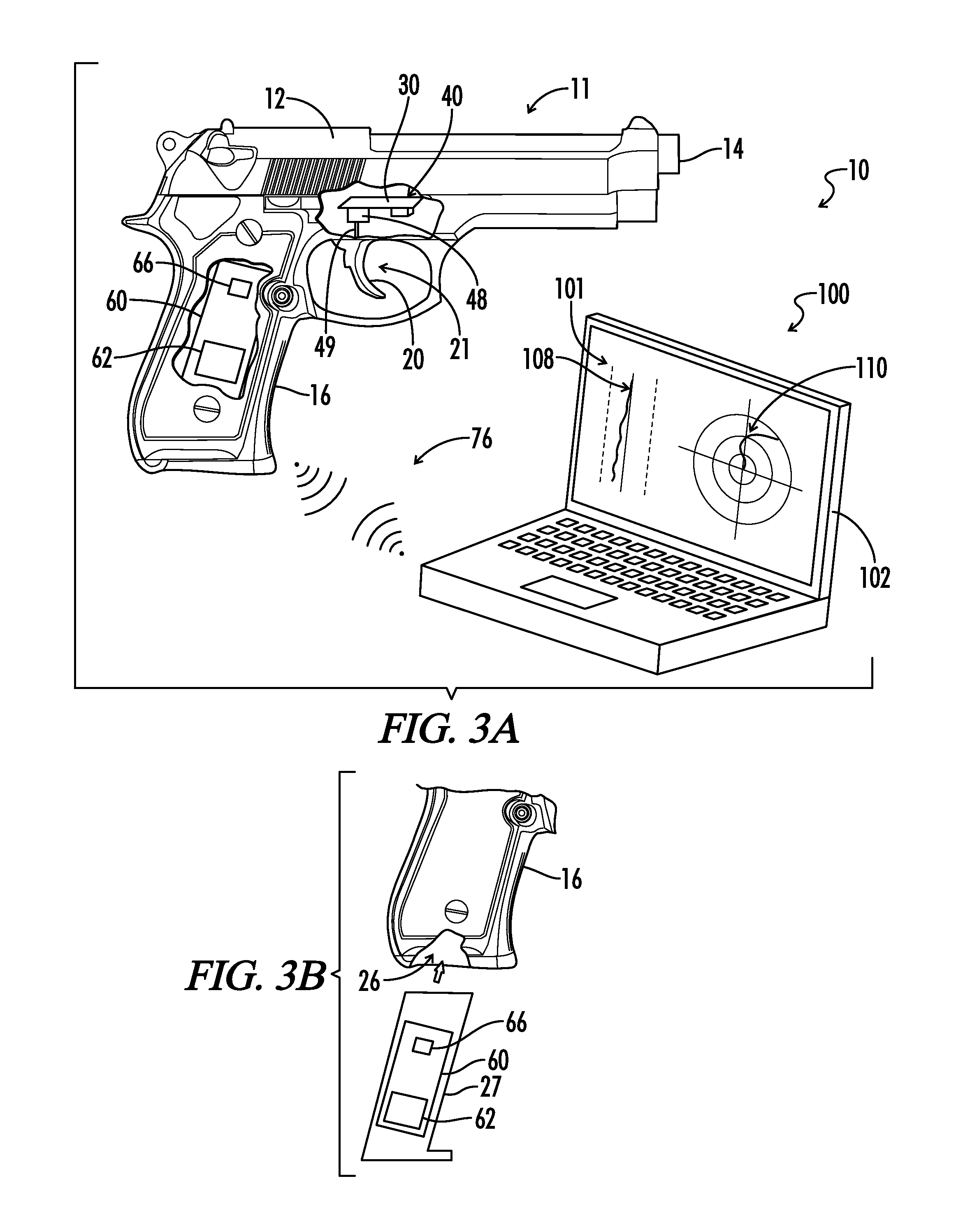
The present invention is a trigger pull training system that allows a user to monitor the user's own input during a trigger pull. Users can also monitor the displacement of the actual barrel during a trigger pull. The system can record information associated with multiple trigger pulls and display it on a screen in a sequential or simultaneous manner. The invention also involves a method for training a shooter by graphically monitoring the actual trigger pull path on a screen. Overall, the invention enhances the user's ability to improve trigger pull technique.

Problems solved by technology

First, the operator generally aims the firearm at a target.
Such barrel movement is undesirable and causes inaccuracy of the fired shot.
Similarly, a firearm operator may inadvertently apply force against the trigger using the operator's finger in a third, generally vertical, direction during a trigger pull, causing the firearm barrel to move up or down relative to the desired target.
Such conventional devices and methods, however, do not monitor actual trigger movement in two dimensions and do not correlate trigger pull path to actual barrel displacement.
Moreover, conventional firearm trigger pull monitoring systems also generally measure only the one-dimensional force applied to the trigger as a function of longitudinal position and do not provide a graphical display of two-dimensional trigger pull path.

Method used


Image

  • Firearm trigger pull training system and methods
  • Firearm trigger pull training system and methods
  • Firearm trigger pull training system and methods

Examples


Embodiment Construction

[0050]While the making and using of various embodiments of the present invention are discussed in detail below, it should be appreciated that the present invention provides many applicable inventive concepts that can be embodied in a wide variety of specific contexts. The specific embodiments discussed herein are merely illustrative of specific ways to make and use the invention and do not delimit the scope of the invention.

[0051]To facilitate the understanding of the embodiments described herein, a number of terms are defined below. The terms defined herein have meanings as commonly understood by a person of ordinary skill in the areas relevant to the present invention. Terms such as “a,”“an,” and “the” are not intended to refer to only a singular entity, but rather include the general class of which a specific example may be used for illustration. The terminology herein is used to describe specific embodiments of the invention, but their usage does not delimit the invention, excep...


PUM


Abstract

A firearm training system provides a firearm body having a trigger and a trigger pull sensor circuit. When the trigger is pulled, the trigger pull sensor circuit provides trigger pull data allowing monitoring of the actual two-dimensional trigger pull path taken by the trigger during the trigger pull. The trigger pull path is graft on a predetermined map together with boundary lines representing a predetermined difference threshold from ideal trigger pull data. The system provides a way to monitor trigger pull path to determine whether the trigger has been pulled laterally and / or the firearm body has moved with respect to a longitudinal axis of the firearm body during the trigger pull. By repeatedly monitoring trigger pulls using the system, a user can train to improve trigger pull technique.

Description

CROSS-REFERENCES TO RELATED APPLICATIONS[0001]This application is a continuation-in-part of co-pending U.S. patent application Ser. No. 12 / 908,420 filed Oct. 20, 2010 entitled “FIREARM TRIGGER PULL TRAINING SYSTEM AND METHODS” which is a continuation-in-part of co-pending U.S. patent application Ser. No. 11 / 504,313, filed Aug. 15, 2006, entitled “SHOOTING TRAINING DEVICE”, both of which are herein incorporated by reference in their entirety.[0002]A portion of the disclosure of this patent document contains material that is subject to copyright protection. The copyright owner has no objection to the reproduction of the patent document or the patent disclosure, as it appears in the U.S. Patent and Trademark Office patent file or records, but otherwise reserves all copyright rights whatsoever.STATEMENT REGARDING FEDERALLY SPONSORED RESEARCH OR DEVELOPMENT[0003]Not ApplicableREFERENCE TO SEQUENCE LISTING OR COMPUTER PROGRAM LISTING APPENDIX[0004]Not ApplicableBACKGROUND OF THE INVENTION...

Claims


Application Information

Patent Timeline
IPC IPC(8): G05G9/047F41A33/00F41A19/00F41A33/06F41A33/02F41J5/02F41G1/38G06F3/0338F41G3/26
CPCF41A33/00F41A33/02F41J5/02F41A33/06F41A19/16F41G3/2655F41G1/38F41A19/00G06F3/0338F41G3/2605A63F2300/8076F41G3/26G05G9/047A63F13/426A63F13/837A63F13/245F41A31/00F41C23/22F41J5/10F41J9/14G09B5/00G09B9/00G09B9/003
Inventor BAXTER, MALCOM
Owner TRIGGERMASTER LLC
Learn More