Compression bandage and method for its manufacture

a compression bandage and manufacturing method technology, applied in the field of compression bandages, can solve the problems of not being able to generate the effect of compression bandages, unable to rework existing compression bandages, and thread loss,

Active Publication Date: 2014-07-15
PETER MUELLER GMBH
View PDF7 Cites 4 Cited by
  • Summary
  • Abstract
  • Description
  • Claims
  • Application Information

AI Technical Summary

Benefits of technology

[0009]A compression bandage according to the invention thus has the tubular main body described above, through which the compression threads run. This tubular main body has a closed form and will not, when used according to its proper purpose, be opened in its circumference either by the medical staff who are applying the bandage or by the patient. In order to adapt the compressive effect individually, at least some of the compression threads that run around the circumference are brought to the outside, out of the main body, so that by changing a fraction of the compression thread that constitutes the external portion, the compressive effect of the compression thread can be specifically adjusted. In particular, a compression bandage that has already been applied in the context of a therapy can be readjusted so that a consistent compressive effect can be achieved even after some of the desired reduction in the circumference of the body part has occurred in the course of the therapy.

Problems solved by technology

Reworking existing compression bandages is not usually possible here, as the cuts that would be necessary in bandages that no longer fit would have the effect that the compression threads would lose their grip, and would no longer be able to generate their effect.
A Velcro fastener of this type is, moreover, very easily manipulated by patients, and this creates a risk that the patient, by changing the circumference of the compression bandage, will change the previously set configuration and therefore the desired compressive effect.

Method used


Image

  • Compression bandage and method for its manufacture
  • Compression bandage and method for its manufacture
  • Compression bandage and method for its manufacture

Examples


Embodiment Construction

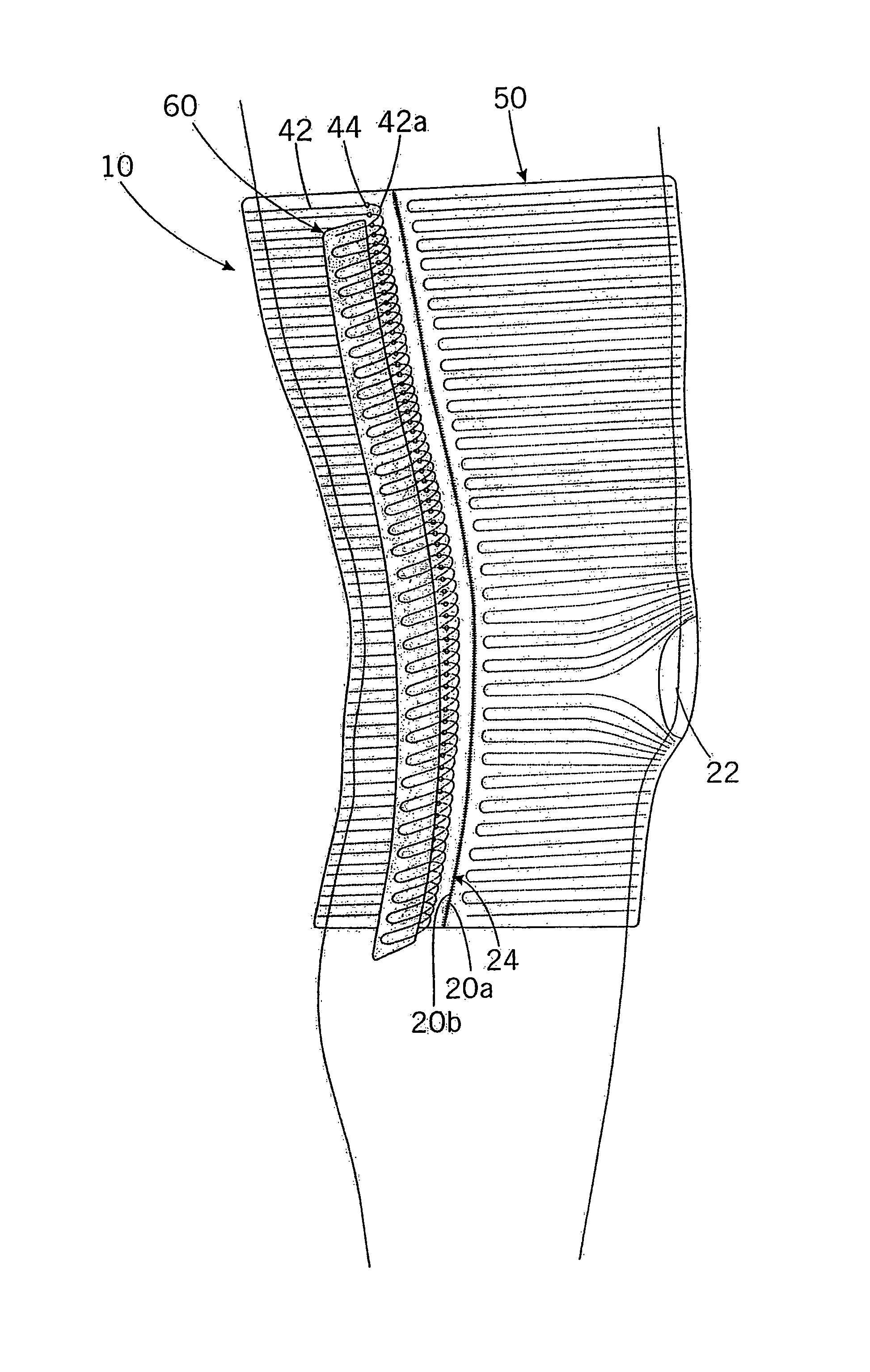
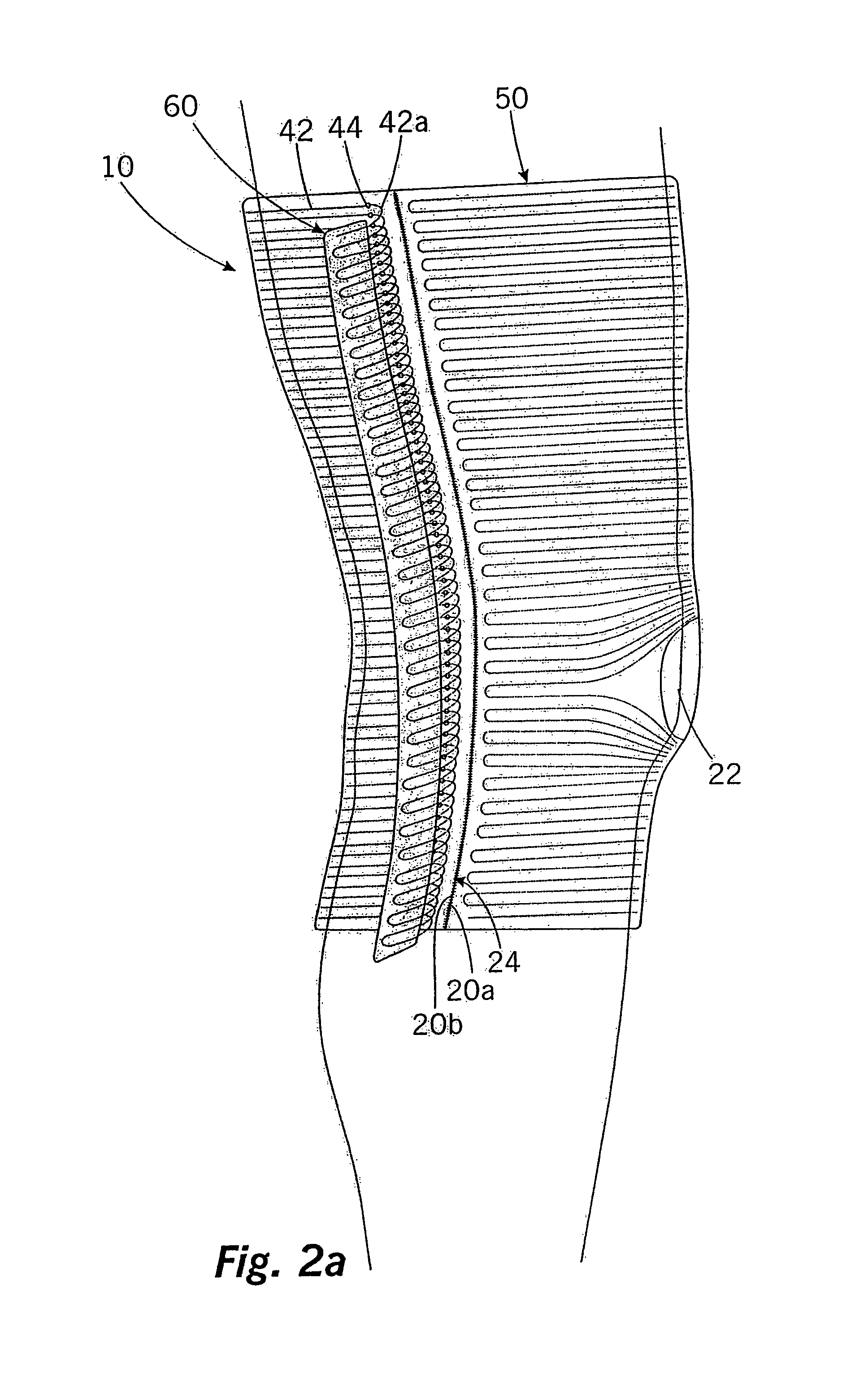
[0035]The embodiment explained below concerns a compression bandage for a leg to be worn in the region of a patient's knee. This type of compression bandage is only to be understood as an example. The method of manufacture described below and the configuration of the compression bandage also apply equally to other kinds of compression bandages, in the form, for instance, of compression stockings or arm bandages.

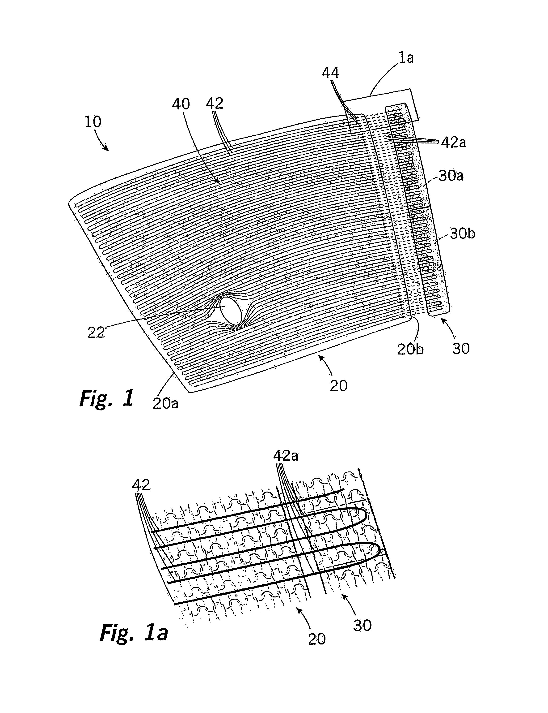
[0036]FIG. 1 illustrates the compression bandage according to the invention in a state where manufacture is not yet complete.

[0037]In this condition, what will later become the compression bandage 10 consists of a flat woven material 20 that will later become the main body 50 and a narrow strip of flat knitted material 30 that will later form the handling section 60. The items of flat knitted material 20, 30 naturally consist, as is illustrated in FIG. 1, of individual rows of stitches, whereby the yarn used may consist of the substantially inelastic polyamide 6.6. This may, ...


PUM

PropertyMeasurementUnit
distanceaaaaaaaaaa
distanceaaaaaaaaaa
wrapping angleaaaaaaaaaa

Abstract

A compression bandage with a tubular, flexible flat material for surrounding a bodily member and with a number of elastic compression threads, whereby this flat material constitutes a main body that can be stretched in the circumferential direction. A number of elastic compression threads run in the plane of the flat material in the direction of the circumference, and create the compressive effect when the compression bandage is applied. At least parts of at least some of the compression threads protrude outside the flat material, allowing the compressive effect to be adjusted by varying the length of each of the protruding external portions.

Description

FIELD OF APPLICATION AND PRIOR ART[0001]This application claims the priority of the German patent application No. 10 2010 011 840.0. The whole disclosure of this prior application is herewith incorporated by reference into this application.[0002]The invention relates to a compression bandage for surrounding a bodily member with a tubular, flexible flat material for surrounding the bodily member and having a number of elastic compression threads. The flat material constitutes a main body of the compression bandage that can be stretched in the circumferential direction. The compression threads extend in the plane of the flat material, passing through the flat material in the circumferential direction; when the compression bandage is applied, they generate the intended compression effect. The invention also relates to a method for manufacturing a compression bandage.[0003]Compression bandages of this type are familiar to the prior art. They are used to compress a patient's bodily membe...

Claims


Application Information

Patent Timeline
Patent Type & Authority Patents(United States)
IPC IPC(8): A61L15/00
CPCA61F13/062A61F13/085
Inventor MUELLER, MARKUS
Owner PETER MUELLER GMBH
Why Eureka
Try Eureka