Drawer guide rail assembly

a technology for guiding rails and drawers, which is applied in the direction of drawers, furniture parts, domestic applications, etc., can solve the problems of deceleration of drawer closing motion, and achieve the effect of reducing the possibility of damage to the guiding device, effective force absorption and drawers, and effective compression of the damping devi

Inactive Publication Date: 2008-06-10
HARN MARKETING
View PDF25 Cites 25 Cited by
  • Summary
  • Abstract
  • Description
  • Claims
  • Application Information

AI Technical Summary

Benefits of technology

[0024]The objective of the guide rail assembly having a damping device of this invention is to provide a substantially quiet, controlled drawer-closing motion that is most importantly, effectively decelerated. As is apparent from the preceding paragraphs, due to the configuration of the guide rail assembly of this invention and particularly the structure and location of the damping device and channel guide with sliding member, deceleration of the drawer-closing motion is achieved without direct contact between the outer pull out guide protrusion and the damping device. Also, this would allow for the drawer-closing force to be partially absorbed by the sliding member as it slides within the channel guide with the remainder of the drawer-closing force absorbed due to compression of the damping device. This would not only result in effective deceleration of the drawer closing motion but also protects the damping device, both its cylinder body and rod, from being damaged, therefore enabling it to be longer lasting.
[0025]Additionally, the configuration of the channel guide with sliding member locating a distal end of the damping device rod within ensures that the linear movement of the damping device rod as it is being pushed into the damping device cylinder body is consistently along the same axis. This is possible due to the sliding member being slidably mounted within the channel guide, therefore allowing the sliding movement of the sliding member to be completely guided by the channel guide. Obviously, this leads to more effective compression of the damping device and as such, more effective force absorbing and drawer closing motion deceleration.
[0026]Furthermore, due to the position of the stopper (on the fixed rail in the first aspect and on the horizontal flange of the mounting bracket in the other aspect) adjacent the channel guide such that the stopper is relative to the rear travel limit position of the sliding member within the channel guide, when drawer is in a fully closed position, the outer pull out guide protrusion rests against the stopper thus, preventing the sliding member from being slammed against the damping device. Again, this would lessen the possibility of damage to the damping device.
[0027]The versatility of this guide rail assembly is also greatly increased as variations in length of rail elements can be easily accommodated by simply re-locating the stopper (on the fixed rail in the first aspect and on the horizontal flange of the mounting bracket in the other aspect) such that it is always positioned adjacent the damping device and channel guide with sliding member so as to be forward relative to the rear travel limit position of the sliding member within the channel guide. This advantageous feature therefore, allows the assembly to be used with rail elements of varying lengths without the need for substantial re-designing or re-sizing of any of the essential components, namely, the damping device, channel guide with sliding member, stopper or outer pull out guide protrusion.

Problems solved by technology

During a closing action of the assembly, the outer pull out guide is caused to slide in a drawer-closing direction and when the protrusion reaches and contacts the sliding member outer portion, the sliding member travels within the channel guide against the resilience of the damping device and causes deceleration of the drawer-closing motion.

Method used


Image

  • Drawer guide rail assembly
  • Drawer guide rail assembly
  • Drawer guide rail assembly

Examples


Embodiment Construction

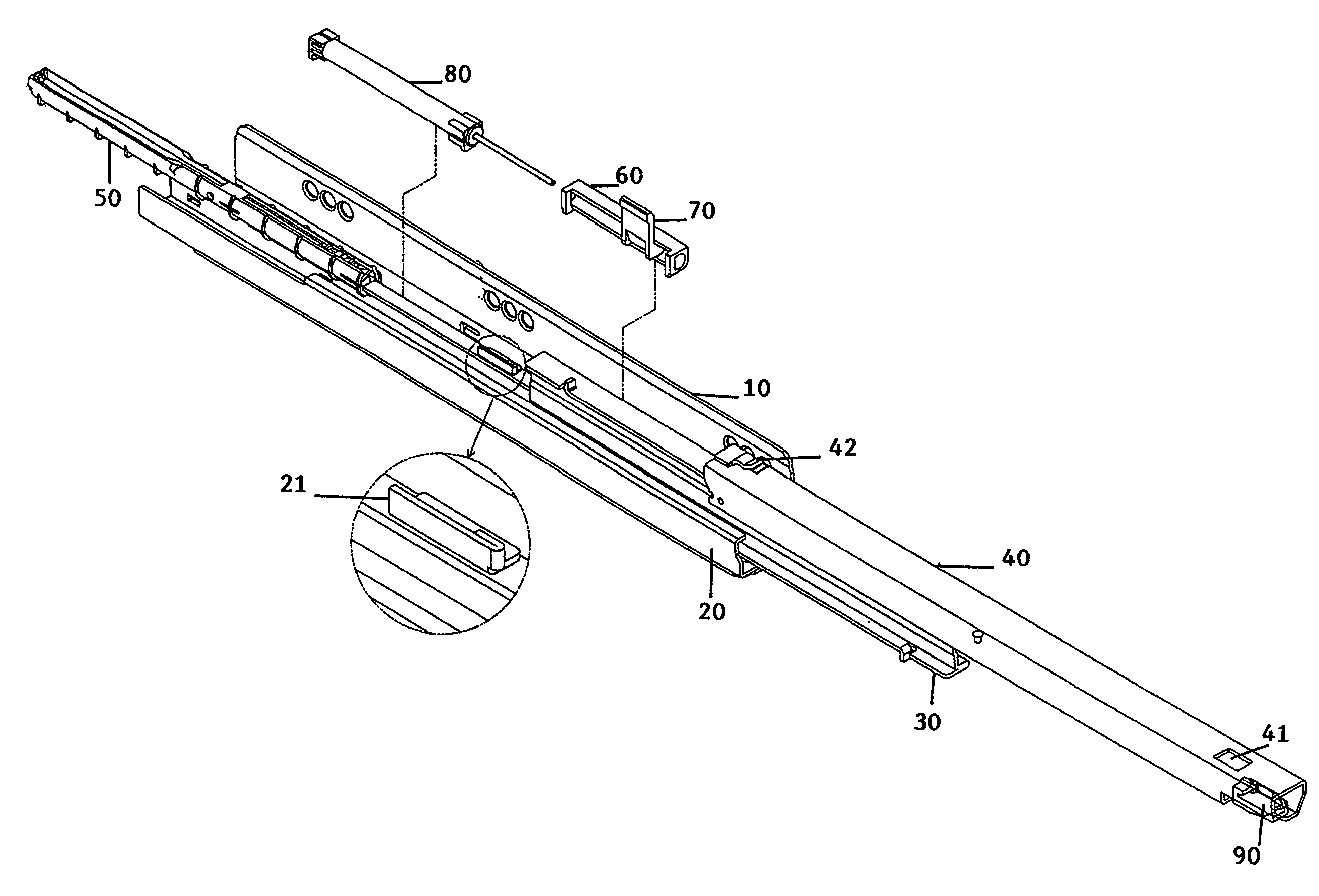
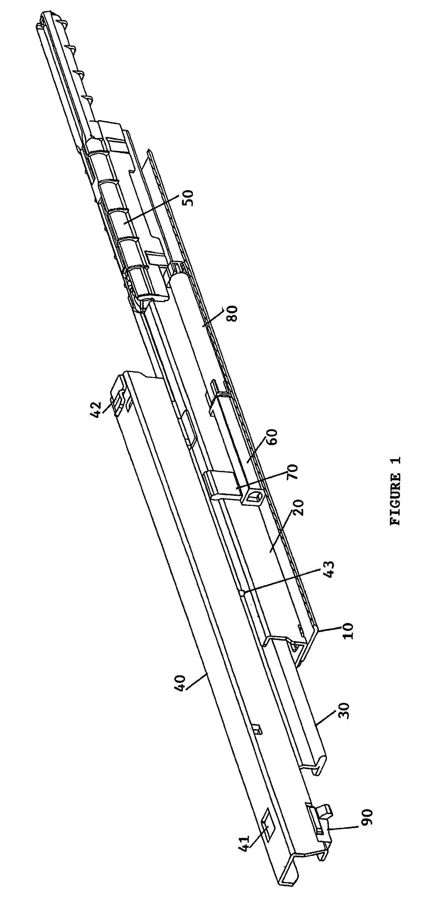
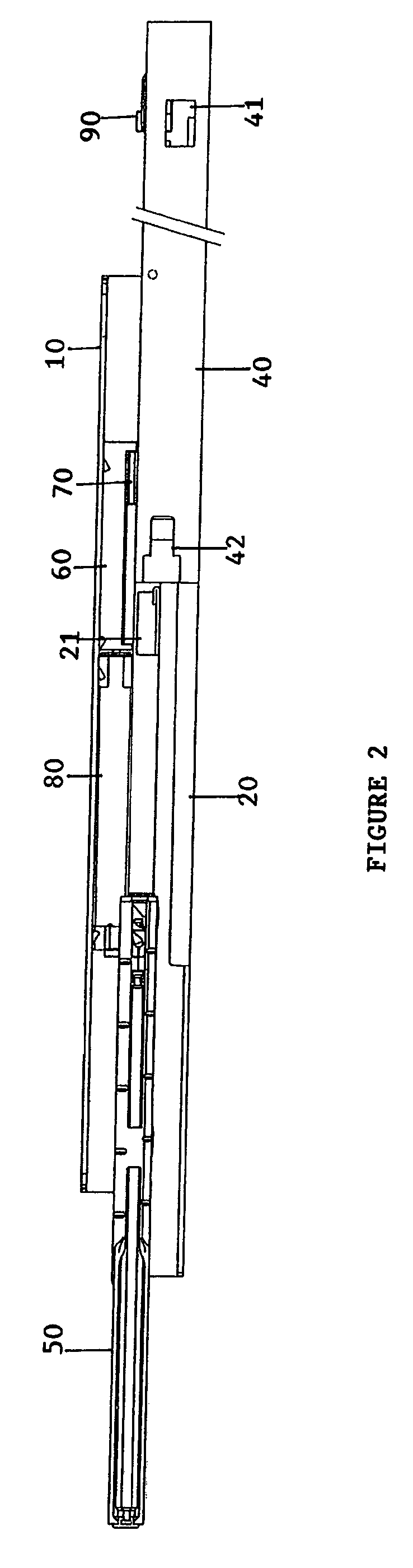
[0051]FIGS. 1 to 9 shows a first embodiment of a guide rail assembly of the present invention having a damping device 80 assembled therein. This guide rail assembly comprises of a mounting bracket 10 for fixing the assembly to an enclosure, a fixed rail 20 mounted on the mounting bracket 10, an intermediate rail 30 and an outer pull out guide 40 secured to the drawer side. The fixed rail 20 and outer pull out guide 40 each have a slidable housing (not shown) having a plurality of rollers, which enables the intermediate rail 30 to be slidable on the fixed rail 20 and the outer pull out guide 40 to be in turn slidable on the intermediate rail 30, as shown in FIGS. 1 and 3. In this first embodiment, a damping device 80 and a channel guide 60 with sliding member 70 are mounted on and along the mounting bracket 10 adjacent the fixed rail 20.

[0052]FIGS. 3, 6A and 6B shows a mounting bracket 10 formed from sheet metal into a substantially L-section comprising of a vertical flange and a hor...


PUM


Abstract

A guide rail assembly for slidably opening and closing a drawer within an enclosure is disclosed. The assembly comprises a mounting bracket (10) for fixing the assembly to the enclosure, a fixed rail (20) on the mounting bracket for receiving an intermediate rail (30), an intermediate rail capable of sliding back and forth relative to the fixed rail, an outer pull out guide (40) for attachment to the drawer and being capable of sliding back and forth on the intermediate rail relative to the intermediate rail and the fixed rail, a protrusion (43) on the bottom surface of the outer pull out guide, a damping device (80) and a channel guide (60) disposed along the mounting bracket adjacent the fixed rail. The damping device is resiliently compressible in a lengthwise direction and the channel guide is provided with a sliding member (70). The sliding member includes an inner portion (71) that travels within the guide and an outer portion (72) that extends outwardly from the guide so as to be contactable by the pull out guide protrusion. The inner portion of the sliding member locates an end (82) of the damping device that can be pushed inwardly to provide damping. During a closing action of the assembly, the outer pull out guide is caused to slide in a drawer-closing direction and when the protrusion reaches and contacts the sliding member outer portion, the sliding member travels within the channel guide against the resilience of the damping device and causes deceleration of the drawer-closing motion.

Description

[0001]This invention relates to a guide rail assembly for use in the furniture industry, and more particularly in a drawer that is slidably opened and closed.[0002]Drawer guide rails are components in common every day use, such as for drawers in desks or cabinets, and for industrial use such as pull out storage shelves at a warehouse, cash registers at a supermarket, automated teller machines at banking kiosks, electronic equipment at telephone switching stations and so on.DESCRIPTION OF THE PRIOR ART[0003]Guide rail systems are provided for drawers to be either partially or fully opened or closed and typically consist of a bracket for fixing the system to the article of furniture, a fixed rail mounted on the bracket, a pull-out rail attached to the side of the drawer, and preferably an intermediate rail in between the fixed and pull-out rails. The intermediate rail is slidable over the fixed rail and the pull-out rail is slidable over the intermediate rail normally due to slidable ...

Claims


Application Information

Patent Timeline
Patent Type & Authority Patents(United States)
IPC IPC(8): A47B88/00A47B88/493A47B88/04
CPCA47B88/047A47B2210/0032A47B2210/0056A47B2210/0059A47B88/467
Inventor LAM, HARN LIANLAM, HARN YAN
Owner HARN MARKETING
Why Eureka
Try Eureka