
Intervertebral disc and insertion methods therefor

a technology of intervertebral discs and insertion methods, which is applied in the field of cervical intervertebral disc implants, can solve the problems of undesirable progressive fusion of long sequences of vertebrae, significant pain to individuals suffering from conditions, etc., and achieve the effects of facilitating long-term fixation, preventing over-insertion, and facilitating long-term fixation to endplate bones

Active Publication Date: 2014-07-15
HOWMEDICA OSTEONICS CORP
View PDF258 Cites 12 Cited by
  • Summary
  • Abstract
  • Description
  • Claims
  • Application Information

AI Technical Summary

Benefits of technology

The present invention provides an intervertebral disc implant with an anterior wall that serves as a vertebral body stop to prevent over-insertion and posterior migration of the implant. The implant also includes protrusions with outwardly laterally facing surfaces with a vertically extending channel or groove for engagement with instruments. The implant may be mounted to an insertion tool that slides along reference pins and includes upper and lower guide slots or openings to distract the disc space for easy insertion of the implant. The technical effects of the invention include improved stability, reduced risk of complications, and simplified and efficient surgical procedures.

Problems solved by technology

This degeneration of this critical disc material, from the hydrated, elastomeric material that supports the separation and flexibility of the vertebral bones, to a flattened and inflexible state, has profound effects on the mobility (instability and limited ranges of appropriate motion) of the segment, and can cause significant pain to the individual suffering from the condition.
Unfortunately, until the advent of spine arthroplasty devices, the only methods known to surgeons to maintain the necessary disc height necessitated the immobilization of the segment.
Either way, however, it is clear that a progressive fusion of a long sequence of vertebrae is undesirable from the perspective of the patient's quality of life as well as from the perspective of pushing a patient to undergo multiple operative procedures.

Method used


Image

  • Intervertebral disc and insertion methods therefor
  • Intervertebral disc and insertion methods therefor
  • Intervertebral disc and insertion methods therefor

Examples


Embodiment Construction

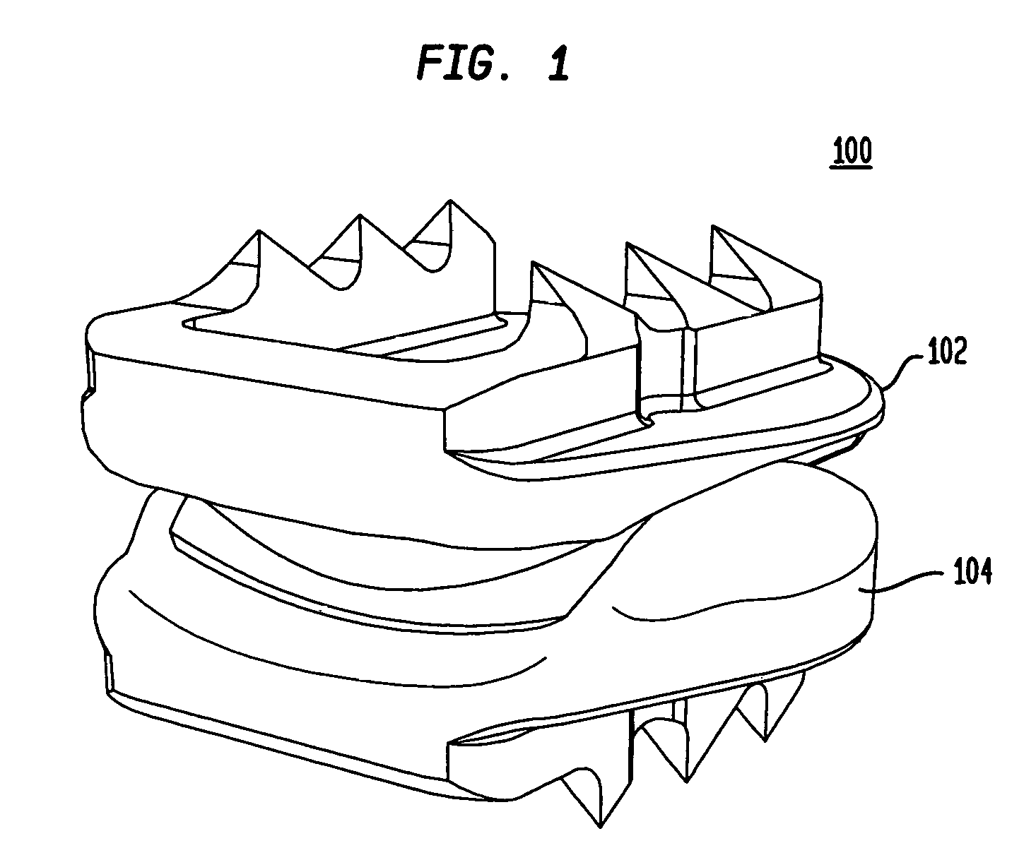
[0081]Referring to FIG. 1, in certain preferred embodiments of the present invention, an intervertebral disc implant 100 includes a top element 102 and a bottom element 104. As will be described in more detail below, the top and bottom elements 102, 104 have opposing articulating surfaces that engage one another. The intervertebral disc implant is adapted to be inserted into a disc space between adjacent vertebrae.

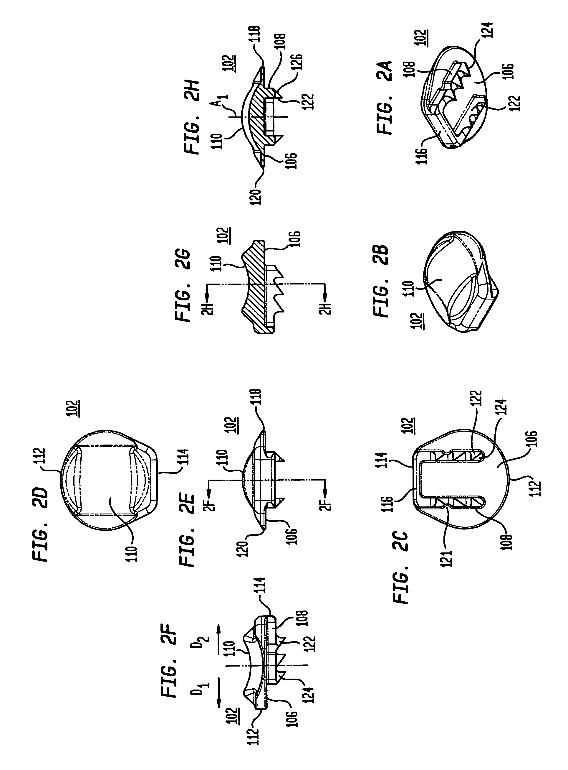
[0082]Referring to FIGS. 2A-2H, the top element 102 includes a first bone engaging surface 106 having protrusions 108A, 108B and a second articulating surface 110. Referring to FIGS. 2C and 2D, the top element has a posterior end 112 and an anterior end 114. As shown in FIGS. 2A and 2C, the two protrusions 108 are interconnected by an anterior wall 116 that extends along the anterior end 114 of the top element. The anterior wall preferably serves as a vertebral body stop to prevent over insertion of the intervertebral disc implant and / or posterior migration of the implant....


PUM


Abstract

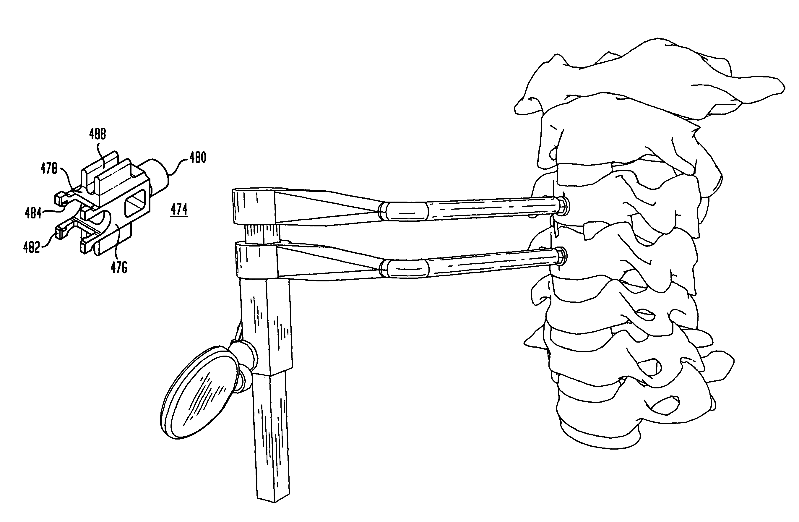
A method of inserting an intervertebral disc implant into a disc space includes accessing a spinal segment having a first vertebral body, a second vertebral body and a disc space between the first and second vertebral bodies. The method includes securing a first pin to the first vertebral body and a second pin to the second vertebral body, using the first and second pins for distracting the disc space, and providing an inserter holding the intervertebral disc implant. The method also desirably includes engaging the inserter with the first and second pins, and advancing the inserter toward the disc space for inserting the intervertebral disc implant into the disc space, whereby the first and second pins align and guide the inserter toward the disc space.

Description

CROSS-REFERENCE TO RELATED APPLICATIONS[0001]The present application claims the benefit of the filing dates of U.S. Provisional Patent Application Nos. 60 / 790,415, filed Apr. 7, 2006, 60 / 721,053, filed Sep. 27, 2005, 60 / 701,306, filed Jul. 21, 2005 and 60 / 685,295, filed May 27, 2005, the disclosures of which are hereby incorporated by reference herein.[0002]The present application relates to U.S. Pat. No. 6,908,484, entitled “Cervical Disc Replacement” and filed on Mar. 6, 2003; U.S. Pat. No. 6,994,728, entitled “Cervical Disc Replacement Method” and filed on Feb. 11, 2004; United States Patent Application Publication No. 2004 / 0176851, entitled “Cervical Disc Replacement” and filed on Feb. 11, 2004; U.S. Pat. No. 6,994,729, entitled “Cervical Disc Replacement” and filed on Feb. 11, 2004; U.S. Pat. No. 6,997,955, entitled “Cervical Disc Replacement” and filed on Feb. 11, 2004; U.S. Pat. No. 6,972,037, entitled “Cervical Disc Replacement” and filed on Feb. 11, 2004; U.S. Pat. No. 6,97...

Claims


Application Information

Patent Timeline
Patent Type & Authority Patents(United States)
IPC IPC(8): A61F2/44
CPCA61F2002/30884A61B2019/444A61F2002/449A61F2/4684A61B17/1735A61F2002/448A61B2019/5416A61F2002/30713A61F2002/4619A61F2/0095A61F2230/0095A61B2019/446A61B2017/0046A61F2002/4628A61B17/1671A61F2002/4687A61F2002/30301A61F2250/0087A61B2019/545A61B17/1757A61F2002/3071A61B17/025A61F2/4611A61B2017/0256A61B2019/461A61F2250/0085A61F2002/4627A61F2/4425A61B2019/5404A61F2002/30841A61B2090/3904A61B2090/3916A61B90/92A61B90/94A61B2090/061A61B2090/395A61B90/90A61F2220/0016A61F2/4603A61F2/442A61F2002/30716A61F2002/4622
Inventor ERRICO, JOSEPH P.DUDASIK, MICHAEL W.ERRICO, THOMAS J.ZUBOK, RAFAIL
Owner HOWMEDICA OSTEONICS CORP
Learn More