
Current sensing resistor

a resistor and current sensing technology, applied in the direction of resistor details, resistor mounting/supporting, instruments, etc., can solve the problems of resistance deviation of resistor products and inability to meet the requirement for high resistance precision, and achieve the effect of improving consistent resistan

Active Publication Date: 2014-07-15
CYNTEC
View PDF13 Cites 4 Cited by
  • Summary
  • Abstract
  • Description
  • Claims
  • Application Information

AI Technical Summary

Benefits of technology

[0010]The present invention provides a current sensing resistor, which has improved consistent resistance before and after a soldering layer is applied.

Problems solved by technology

Since the soldering layer is applied onto the resistor after the measurement and adjustment of the resistance of the resistor has been accomplished, the resistor product suffers from resistance deviation due to the newly applied soldering layer.
Thus the requirement on high resistance precision cannot be complied with.

Method used


Image

  • Current sensing resistor
  • Current sensing resistor
  • Current sensing resistor

Examples


Embodiment Construction

[0037]The present invention will now be described more specifically with reference to the following embodiments. It is to be noted that the following descriptions of preferred embodiments of this invention are presented herein for purpose of illustration and description only; it is not intended to be exhaustive or to be limited to the precise form disclosed.

[0038]A current sensing resistor device according to an embodiment of the present invention is illustrated in a schematic prospective view as shown in FIG. 4A, a schematic cross-sectional view as shown in FIG. 4B, which is taken along a I-I′ line of FIG. 4A, and a schematic side view, as shown in FIG. 4C.

[0039]As shown in FIGS. 4A and 4B, the current sensing resistor 400 includes a resistor plate 420 and an electrode structure 430. The resistor plate 420 is created with openings at opposite sides thereof, and the electrode structure 430 is provided in a stack form onto the resistor plate 420 by way of, for example, welding or ele...


PUM


Abstract

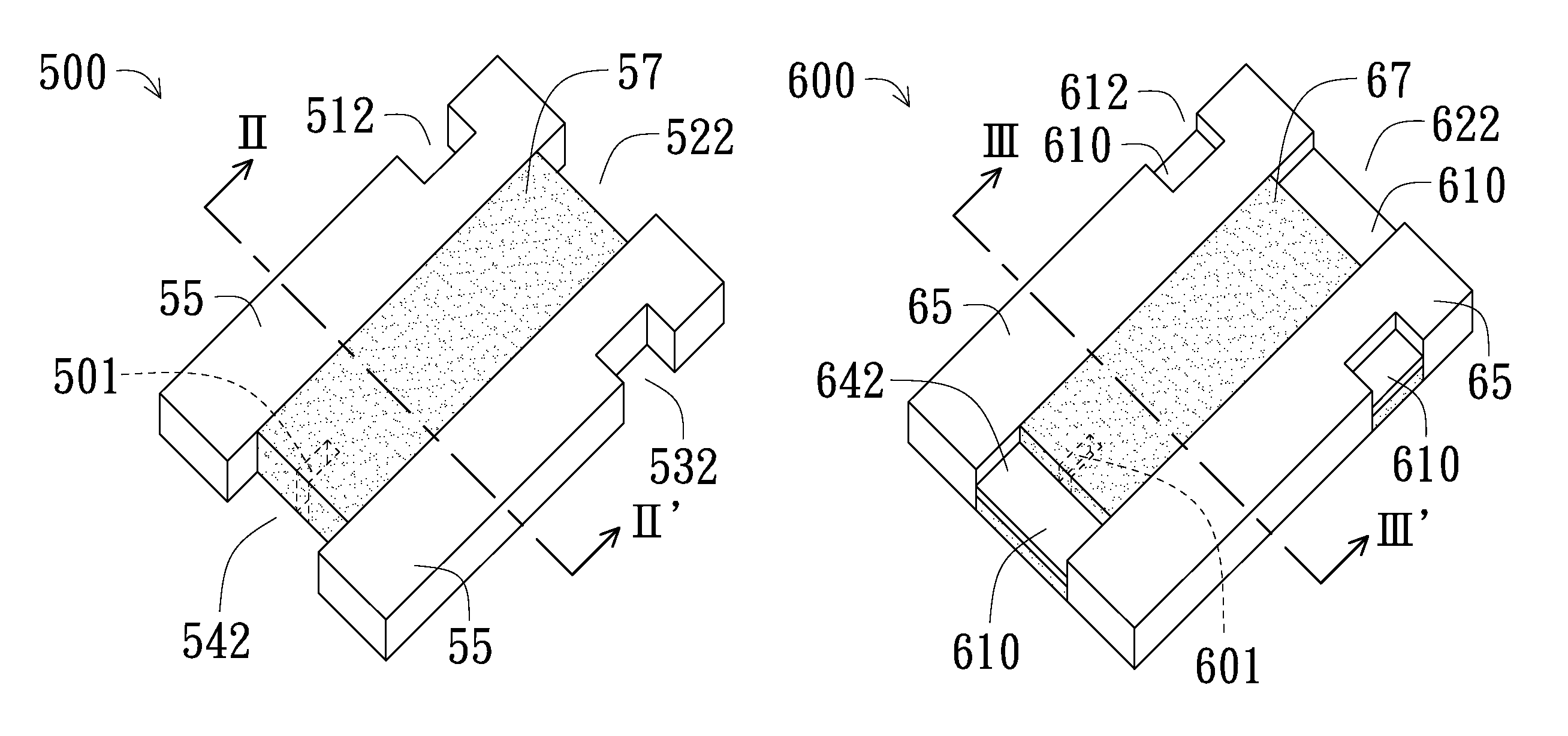
A resistor device includes a resistor plate and an electrode structure. The electrode structure includes an electrode layer and an auxiliary layer. The electrode layer is disposed at a first face of the resistor plate and includes a first portion and a second portion overlying a first side and a second side of the resistor plate, respectively, and a current path is conducted between the first portion and the second portion through the resistor plate. The auxiliary layer is disposed at a second face of the resistor plate and includes at least a first block and a second block overlying the first side of the resistor plate, and at least a third block overlying the second side of the resistor plate, wherein the first, second and third blocks of the auxiliary layer are separated from one another so that any current flow among the blocks is blocked.

Description

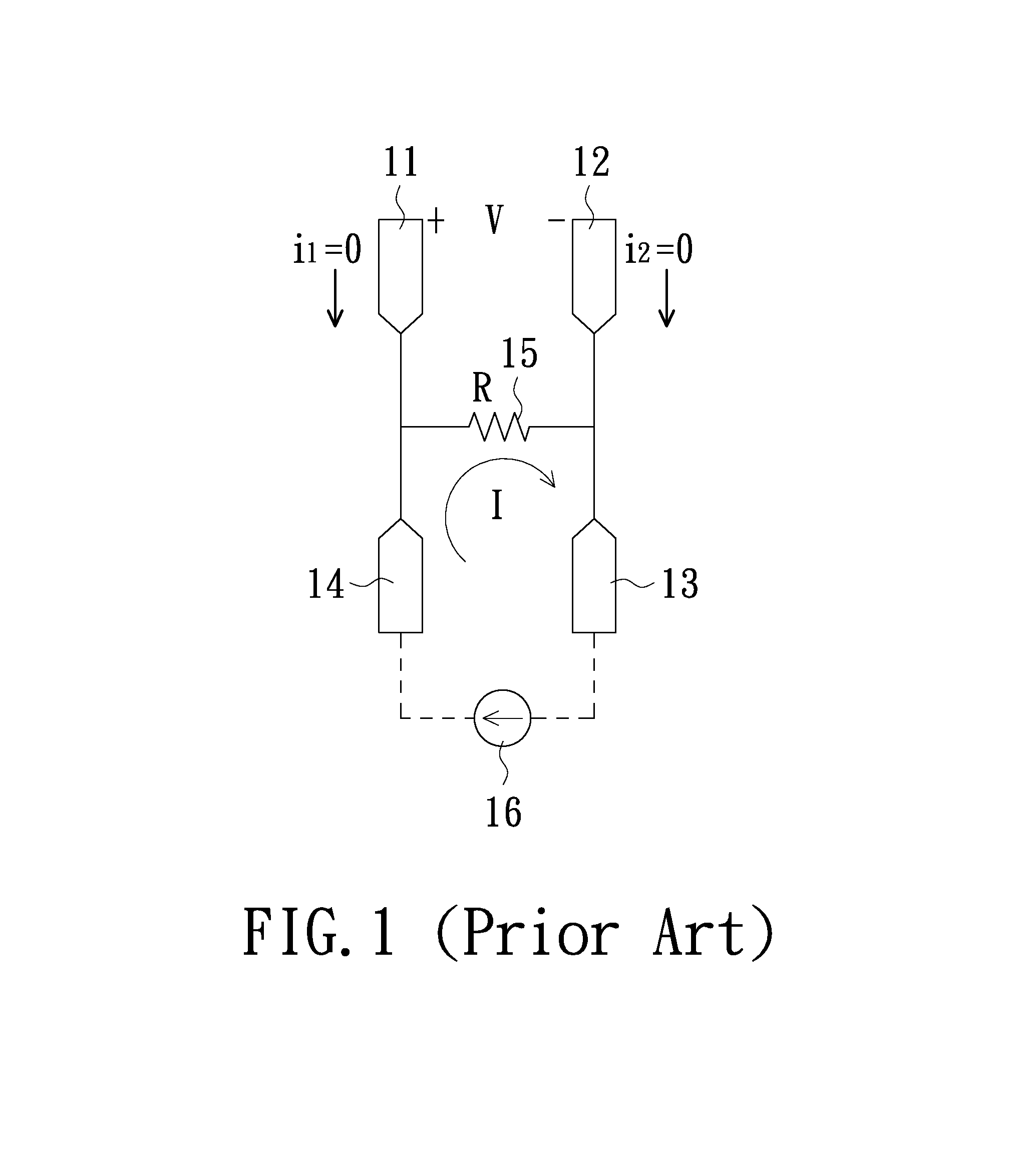
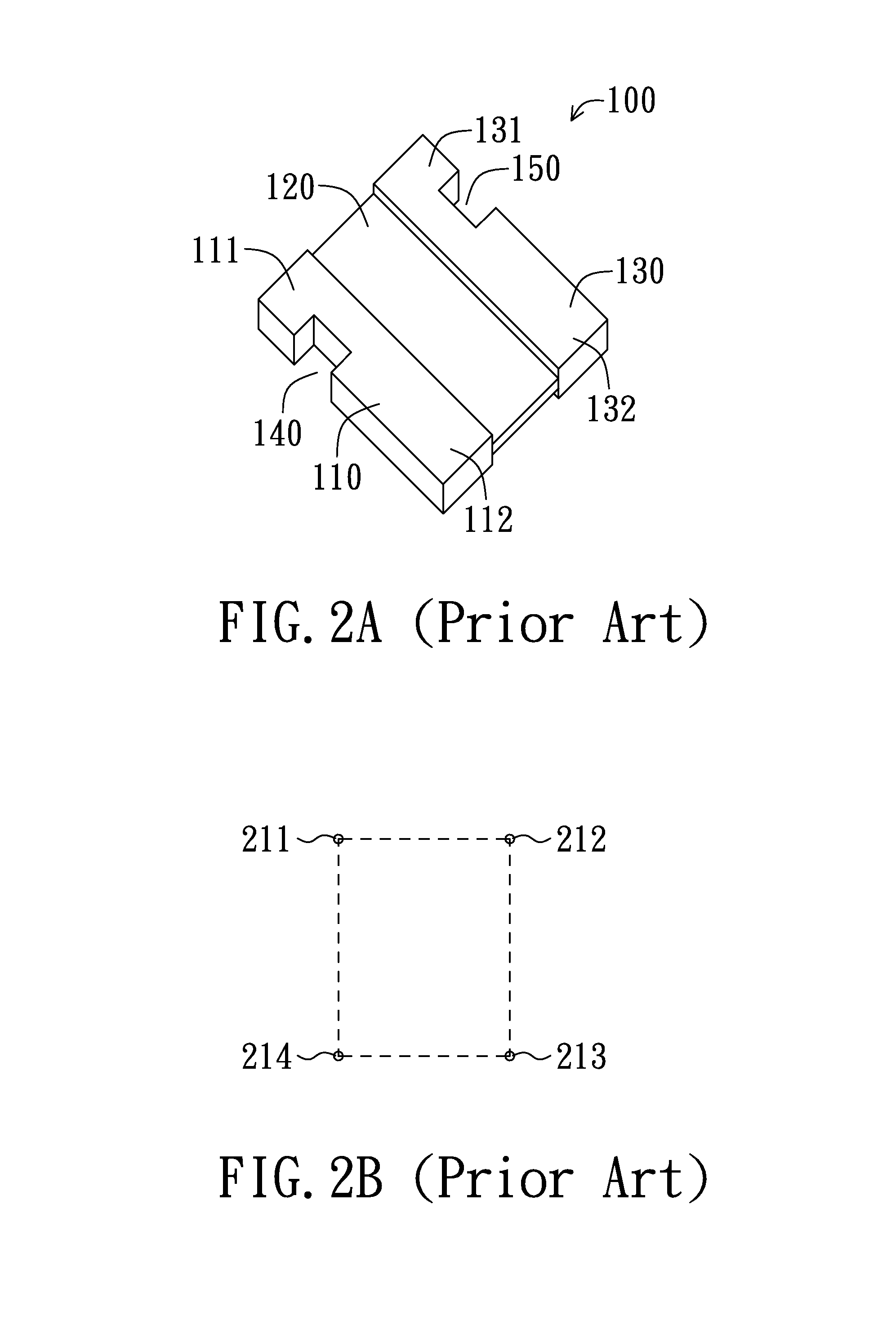
CROSS-REFERENCE TO RELATED APPLICATIONS[0001]The present application is a continuation-in-part application claiming benefit from a parent U.S. patent application Ser. No. 12 / 779,656 and filed May 13, 2010, contents of which are incorporated herein for reference.FIELD OF THE INVENTION[0002]The present invention relates to a resistor device, and more particularly to a resistor device adapted to current sensing.BACKGROUND OF THE INVENTION[0003]A current sensing resistor, when serially connected to a load and applied current thereto, results in a voltage drop which may be measured and referred to estimate the current intensity. Since the resistance of a current sensing resistor is generally at a milliohm (mOhm) order, high resistance precision, e.g. with deviation within ±1%, is required compared to a common resistor. Accordingly, proper adjustment is generally performed in the manufacturing process of the current sensing resistor after measuring resistance of the newly produced resisto...

Claims


Application Information

Patent Timeline
Patent Type & Authority Patents(United States)
IPC IPC(8): H01C1/012H01C7/13
CPCH01C7/13G01R1/203H01C1/148H01C7/003
Inventor LO, TA-WENLIN, YEN-TING
Owner CYNTEC
Learn More