2D web trilateration

a web trilater and web trilater technology, applied in the direction of direction finders, instruments, location information based services, etc., can solve the problems of inability to respond to various commands by network devices or servers, inability to use intrusive methods to determine network latency,

Active Publication Date: 2014-07-15
THE 41ST PARAMETER
View PDF15 Cites 37 Cited by
  • Summary
  • Abstract
  • Description
  • Claims
  • Application Information

AI Technical Summary

Problems solved by technology

The problem with using such techniques as described by prior systems is that various network devices or servers may not be configured to respond to various commands (such as ping), or may not have a requisite application, such as JavaScript, installed in its browser.
Thus, such intrusive methods of determining network latency may not work unless the various components of the system are configured to accept the various commands.

Method used


Image

  • 2D web trilateration
  • 2D web trilateration
  • 2D web trilateration

Examples


Embodiment Construction

[0027]While preferred embodiments of the invention have been shown and described herein, it will be obvious to those skilled in the art that such embodiments are provided by way of example only. Numerous variations, changes, and substitutions will now occur to those skilled in the art without departing from the invention. It should be understood that various alternatives to the embodiments of the invention described herein may be employed in practicing the invention.

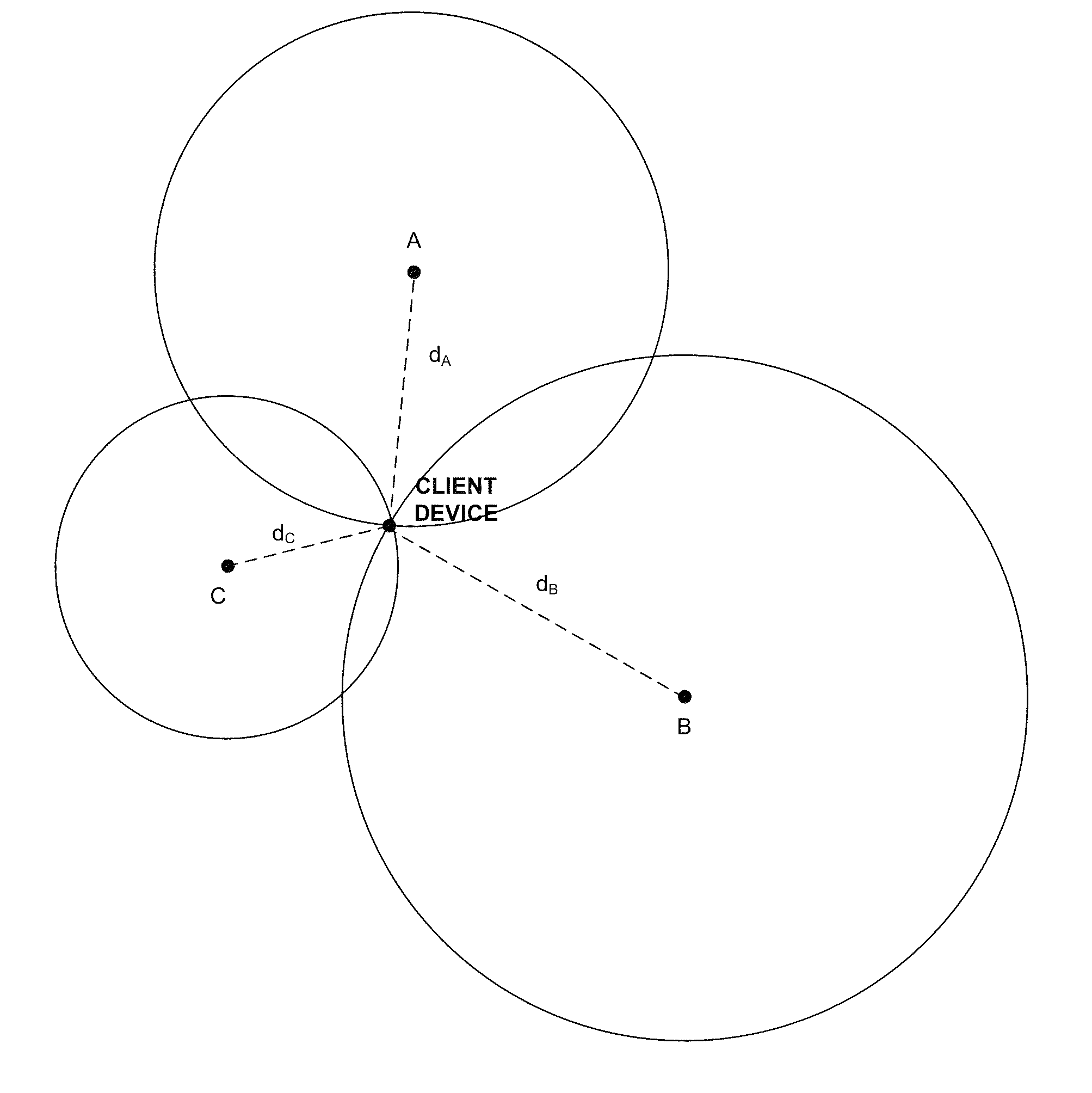
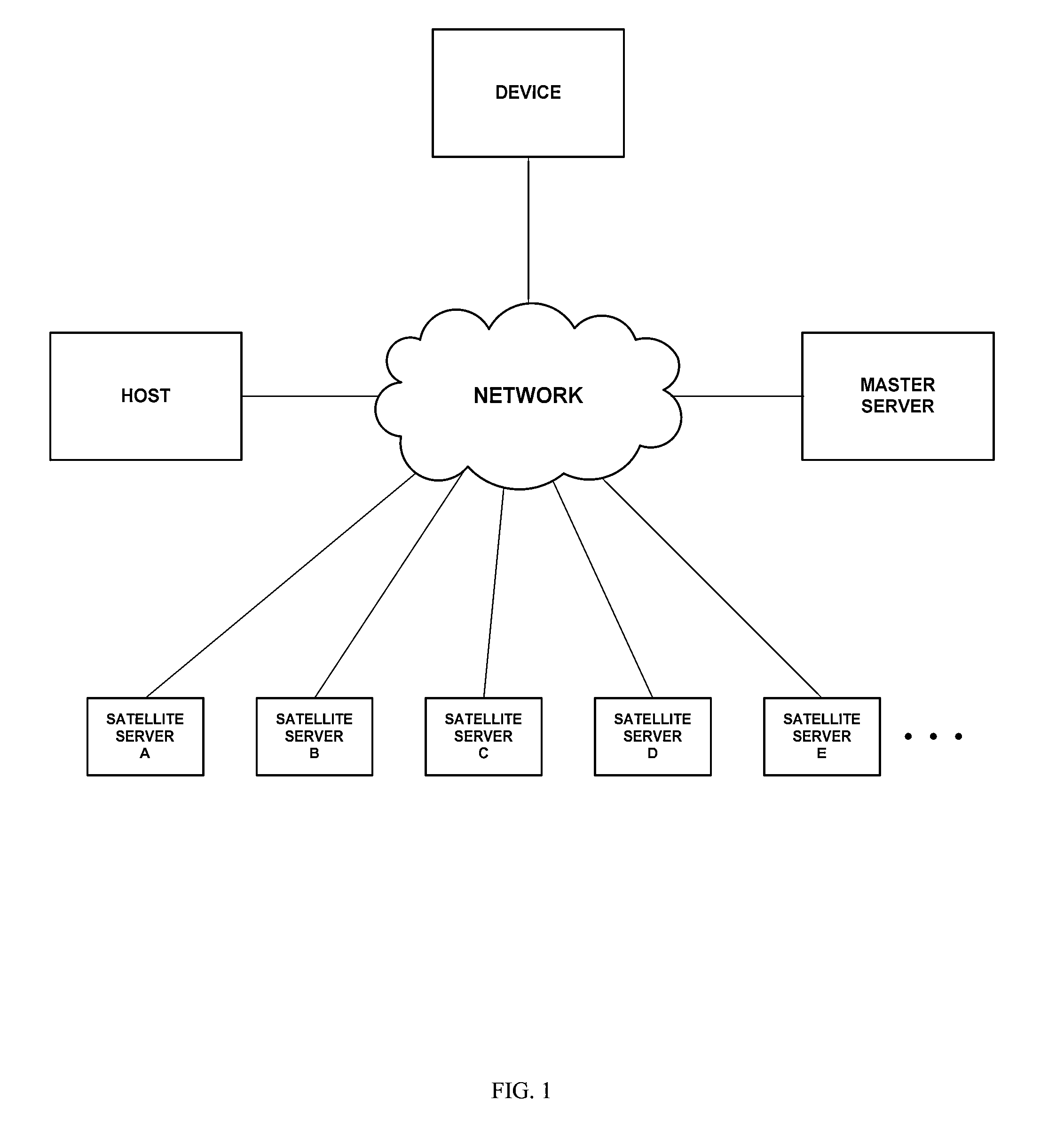
[0028]Referring to the drawings in detail, FIG. 1 shows a system for locating a networked device in accordance with an embodiment of the invention. Such a system may include a device, a host server, a master server, and a plurality of satellite servers (e.g., satellite server A, B, C, D, E, . . . ). Any or all of these components may communicate with one another over a network. In preferable embodiments, all of these components may be communicating over the same network (such as the Internet) while in other embodiments, ...


PUM


Abstract

The invention provides systems and methods of locating a network device based on the time latency between a request by a user device and the receipt of the request by a plurality of satellite servers provided at different locations. Preferably three or more satellites may be employed. The request may be for an item, which may have a known file size, and which may or may not exist. Triangulation techniques may be utilized to determine the location of the device relative to the satellite servers.

Description

CROSS-REFERENCE[0001]This application claims the benefit of U.S. Provisional Application No. 61 / 156,456, filed Feb. 27, 2009, which application is incorporated herein by reference.BACKGROUND OF THE INVENTION[0002]Global positioning systems (GPS) have used 3D trilateration in the past to locate a target. Physical GPS systems have used a minimum of 4 satellites to ascertain longitude, latitude and attitude (3D trilateration). Such systems have been useful for determining the location of a target based on the intersection of various vectors.[0003]Systems have tried to utilize real world trilateration methods to locate a network device. See, e.g., U.S. Patent Publication No. 2008 / 0010367, U.S. Patent Publication No. 2008 / 0101277, U.S. Pat. Nos. 7,436,870, 6,947,978, which are hereby incorporated by reference in their entirety. One previous system utilized commands such as network trace routes or pinging commands to ascertain network latency between a test device and a target device. See...

Claims


Application Information

Patent Timeline
Patent Type & Authority Patents(United States)
IPC IPC(8): G01S5/14
CPCG01S5/0009G01S5/06H04W4/02H04W4/029
Inventor EISEN, ORIPANDICH, STEVEYALOV, RAZ
Owner THE 41ST PARAMETER
Why Eureka
Try Eureka