System integration for feasibility display

a feasibility display and system integration technology, applied in the field of system integration, can solve the problems of improving the time and cost of weapon integration, and achieve the effect of better assessment of air to air engagements

Active Publication Date: 2014-07-22
BAE SYSTEMS PLC
View PDF6 Cites 4 Cited by
  • Summary
  • Abstract
  • Description
  • Claims
  • Application Information

AI Technical Summary

Benefits of technology

[0026]In this way, the same aircraft system can also display whether or not, or to what extent, the aircraft is at risk of being successfully engaged by a weapon carried by a hostile aircraft, which may be a hostile aircraft which the host aircraft is deciding whether or not to engage. The generic algorithm enables the calculation of opposing LSZs and allows better assessment of air to air engagements. This in turn could lead to confident predictions of advantage and likely outcome of engagements.

Problems solved by technology

Such a system significantly improves weapon integration time and cost.

Method used


Image

  • System integration for feasibility display
  • System integration for feasibility display
  • System integration for feasibility display

Examples


Embodiment Construction

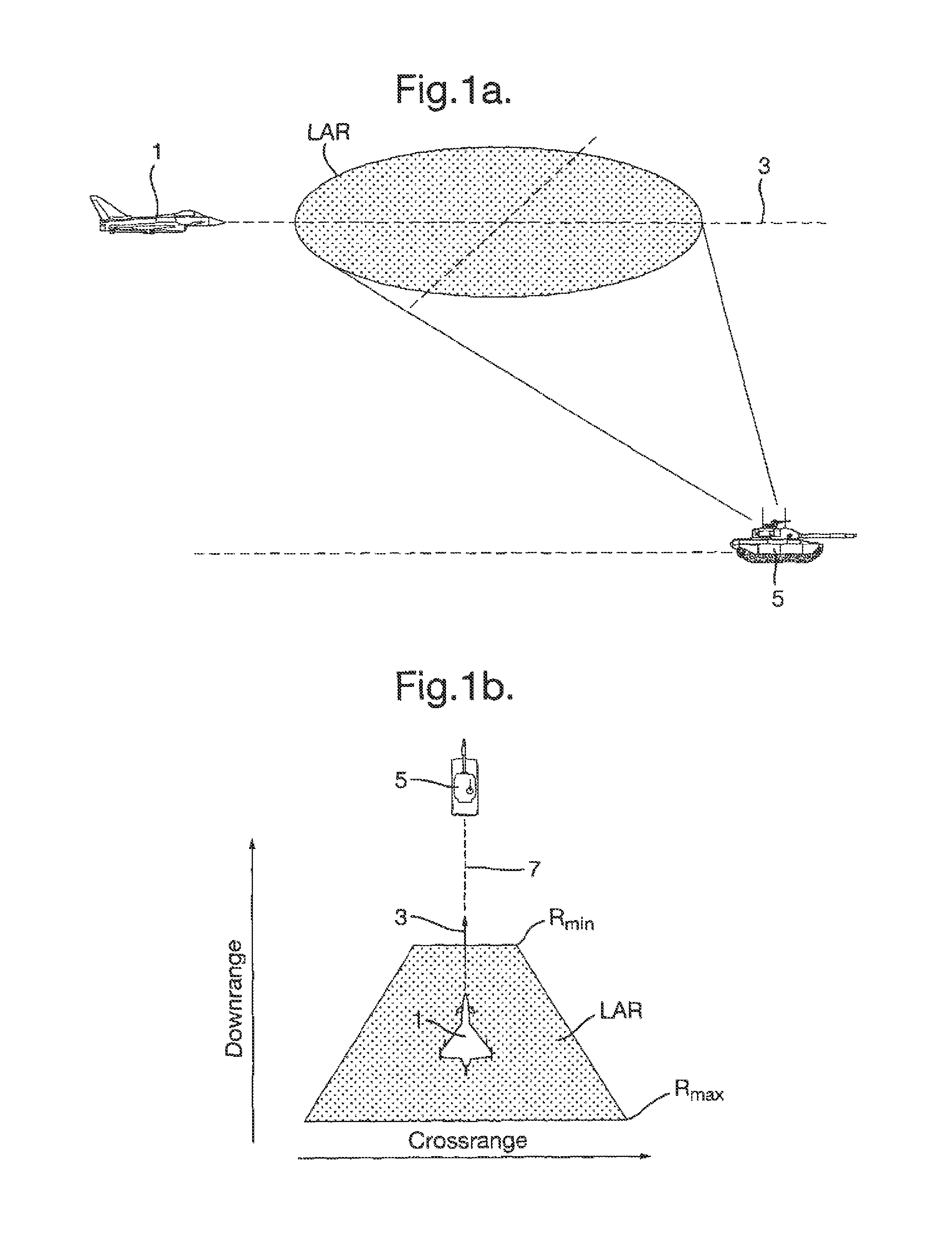
[0033]FIG. 1a shows the LAR in the plane of flight of a launch aircraft 1 flying along a flight path 3 in respect of a target 5 for an air to surface weapon (not shown) loaded on the aircraft. The LAR is calculated to provide cockpit displays in the launch aircraft 1 concerning the feasibility and firing opportunities for the situation. FIG. 1b shows the display generated for the LAR of FIG. 1a, which is in the form of a downrange and cross range display (the shaded area), where the weapon flight path 7 coincides with the aircraft flight path 3; to successfully engage the target 5 as shown in the display, the target must fall inside the shaded LAR. As the aircraft 1 moves in the downrange direction, the displayed LAR is bounded by the minimum and maximum ranges, Rmin and Rmax.

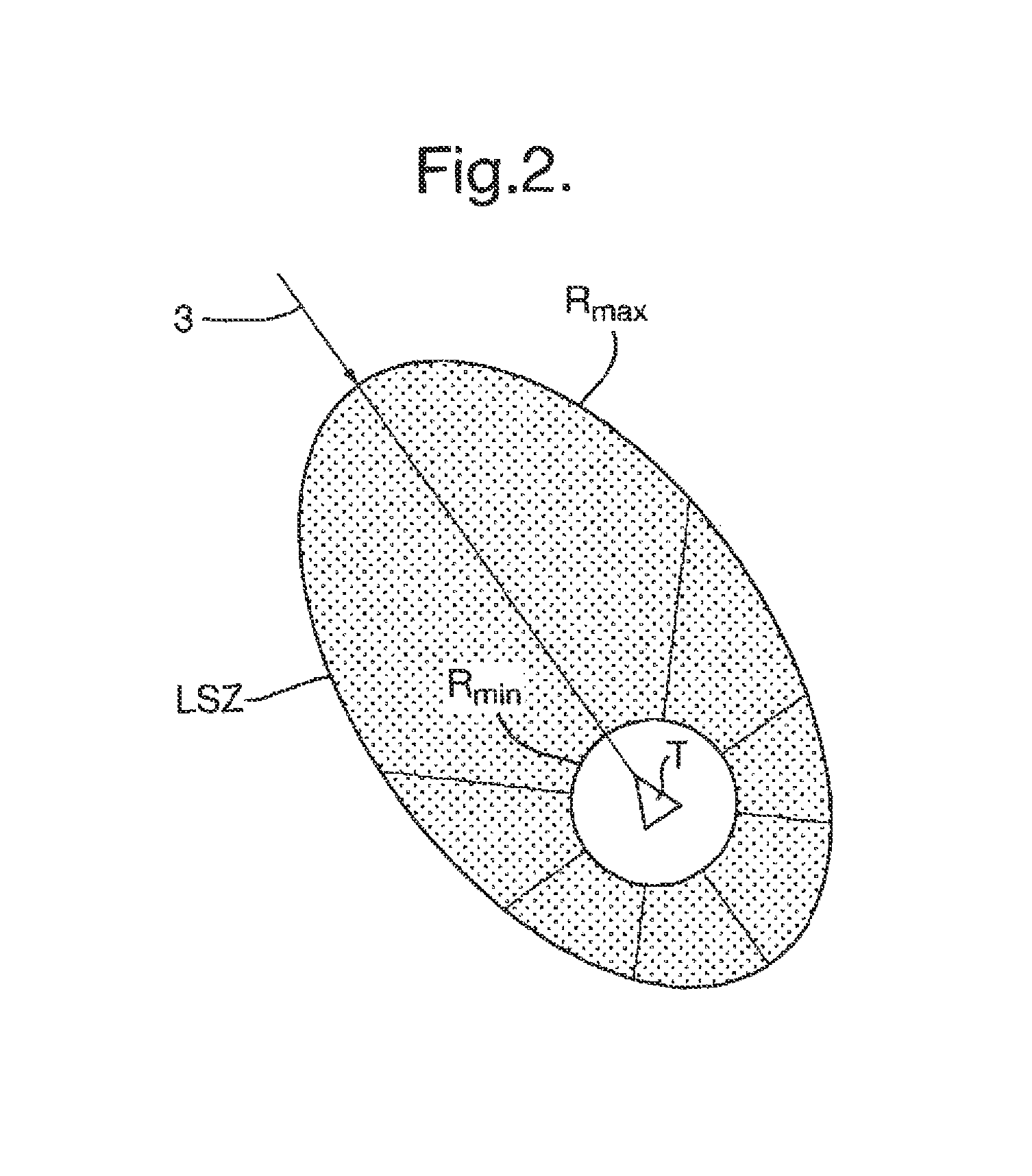
[0034]The LSZ shown in FIG. 2 is the region where the probability of an air to air weapon hitting an airborne target T is above a threshold level. Calculation of the LSZ is more complicated than for the LAR, be...


PUM


Abstract

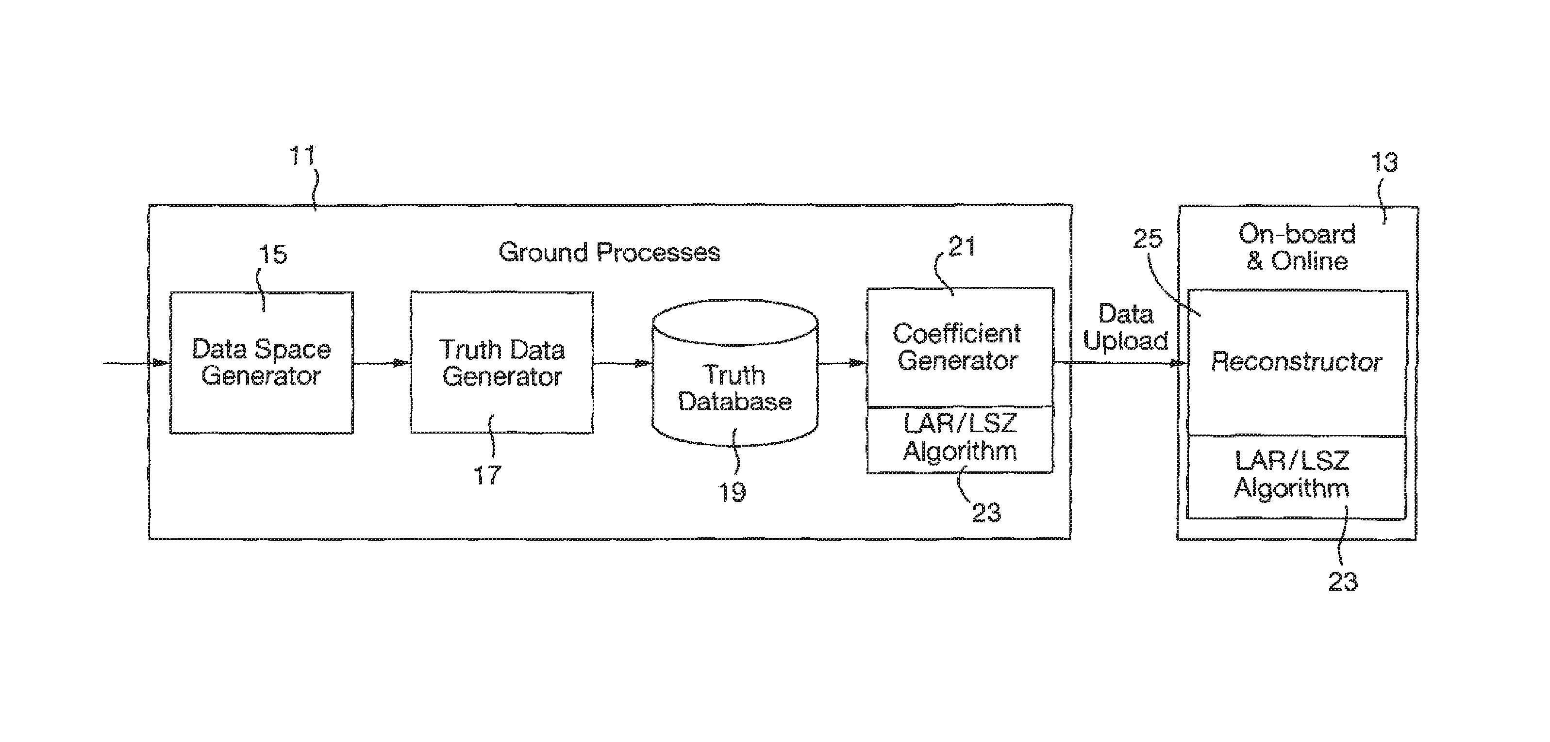
Systems and methods of integrating weapons systems with the aircraft systems of an aircraft carrying the weapon so as to generate on the aircraft in flight a display indicative of the weapon successfully engaging a target are disclosed. The system can include a ground station for generating a database describing the weapon performance envelope, a generator for creating coefficients characteristic of that performance envelope using a generic algorithm and an uploader for uploading the coefficients to the aircraft, and a reconstructor on the aircraft containing the same generic algorithm and adapted to select the coefficients for the algorithm according to the aircraft and target conditions in order to generate the feasibility display, wherein the algorithm is generic to both air to ground and air to air weapons.

Description

RELATED APPLICATIONS[0001]This application is a national phase application filed under 35 USC §371 of PCT Application No. PCT / GB10 / 51323 with an International filing date of Aug. 10, 2010 which claims priority of EP Patent Application 09251978.4 filed Aug. 12, 2009, GB Patent Application 0914109.4 filed Aug. 12, 2009, and GB Patent Application 0921089.9 filed Dec. 2, 2009. Each of these applications is herein incorporated by reference in their entirety for all purposes.FIELD OF THE INVENTION[0002]This invention relates to the integration of systems and, more particularly, to the integration of weapons on complex, highly integrated aircraft.BACKGROUND OF THE INVENTION[0003]Integration of a weapon system with the other systems on an aircraft is a complex and lengthy task, as it affects all the major aircraft systems. Accordingly there is a requirement to improve weapon integration time and affordability.[0004]One of the requirements of weapon integration is to enable the display of in...

Claims


Application Information

Patent Timeline
Patent Type & Authority Patents(United States)
IPC IPC(8): G06F19/00F41G3/22F41G7/00F41G9/00
CPCF41G7/007F41G9/002F41G3/22
Inventor RANAT, BHADRAYU MANHERLALAL-AMERI, MONADL ABD AL-ABBAS MANSOURHAINES, JEFFREY CHRISTOPHER
Owner BAE SYSTEMS PLC
Why Eureka
Try Eureka