
Illumination device and method of implementing illumination device

a technology of illumination device and illumination device, which is applied in the direction of optical elements, instruments, fibre light guides, etc., can solve the problems of inability to maintain the desired optical coupling state, the amount of light loss upon optical coupling is difficult to minimize, and the amount of light loss upon optical coupling is difficult to achieve. , to achieve the effect of facilitating the reduction of the amount of light loss upon optical coupling

Inactive Publication Date: 2014-07-22
OLYMPUS CORP
View PDF13 Cites 2 Cited by
  • Summary
  • Abstract
  • Description
  • Claims
  • Application Information

AI Technical Summary

Benefits of technology

[0012]The present invention has been made in consideration of the above-described situations, and has as its object to provide an illumination device and a method of implementing an illumination device which maintain an optical coupling state capable of easily minimizing the amount of light loss upon optical coupling.
[0014]According to an aspect of embodiments, a method of implementing an illumination device in which after an optical fiber holder holding an optical fiber and a phosphor holder holding a phosphor are relatively positionally adjusted, a bonding material intervening between the optical fiber holder and the phosphor holder is cured to bond the optical fiber holder and the phosphor holder, includes fixing a position of one of the optical fiber holder and the phosphor holder before relatively positionally adjusting the optical fiber holder and the phosphor holder, moving the other of the optical fiber holder and the phosphor holder toward the one so as to abut an end face of the other, which tilts with respect to an optical axis direction on the other side, against distal end faces of adjustment guide members, which tilt with respect to an optical axis direction on the other side, the adjustment guide members being disposed on the end face of the one and having heights based on the end face of the one in an optical axis direction on the one side, adjusting a position of the other relative to a position of the one by tilting the other with respect to the one about the optical axis direction on the one side so that the end face of the other tilts with respect to the distal end faces about the optical axis on the one side, thereby making an optical axis of the optical fiber parallel to an optical axis of the phosphor, adjusting the position of the other relative to the position of the one by moving the other with respect to the one in an X-axis direction perpendicular to the optical axis direction on the one side and a Y-axis direction perpendicular to the optical axis direction on the one side and the X-axis direction so that the end face of the other slides with respect to the distal end faces about the optical axis on the one side in the X-axis direction and the Y-axis direction while keeping abutting against the distal end faces, thereby arranging the optical axis of the phosphor and the optical axis of the optical fiber on one line and bonding the optical fiber holder and the phosphor holder by curing the bonding material while causing the adjustment guide members to prevent the optical fiber holder and the phosphor holder from tilting.
[0015]According to an aspect of embodiments, a method of implementing an illumination device in which after an optical fiber holder holding an optical fiber and a phosphor holder holding a phosphor are relatively positionally adjusted, a bonding material intervening between the optical fiber holder and the phosphor holder is cured to bond the optical fiber holder and the phosphor holder, includes fixing a position of one of the optical fiber holder and the phosphor holder before relatively positionally adjusting the optical fiber holder and the phosphor holder, moving the other of the optical fiber holder and the phosphor holder toward the one so as to abut an end face of the other against adjustment guide members, the adjustment guide members being disposed on the end face of the one and being plastic-deformable when being pressed, tilting the other with respect to the one about an optical axis on the one side while causing the end face of the other to press and plastic-deform the adjustment guide members, thereby making an optical axis of the optical fiber parallel to an optical axis of the phosphor, adjusting a position of the other relative to a position of the one by sliding the other with respect to the adjustment guide members about the optical axis on the one side in an X-axis direction perpendicular to the optical axis direction on the one side and a Y-axis direction perpendicular to the optical axis direction on the one side and the X-axis direction while keeping the end face of the other abutting against the adjustment guide members, thereby arranging the optical axis of the phosphor and the optical axis of the optical fiber on one line, adjusting the position of the other relative to the position of the one by moving the other against the one in the optical axis direction on the one side so that the end face of the other presses the adjustment guide members about the optical axis of the optical fiber in the optical axis direction on the one side and plastic-deforms the adjustment guide members and bonding the optical fiber holder and the phosphor holder by curing the bonding material while causing the adjustment guide members to prevent the optical fiber holder and the phosphor holder from tilting.

Problems solved by technology

If the optical coupling is not ensured as desired, it is difficult to minimize the amount of light loss upon optical coupling.
In addition, if the thickness of the adhesive is uneven, or the whole adhesive is not uniformly irradiated with the UV irradiation light, the holders to be bonded may shift when the adhesive is cured.
Even if the optical fiber and the PD are sufficiently optically coupled, the shift of the holders to be bonded may make it impossible to maintain the desired optical coupling state.

Method used


Image

  • Illumination device and method of implementing illumination device
  • Illumination device and method of implementing illumination device
  • Illumination device and method of implementing illumination device

Examples


Embodiment Construction

[0028]The embodiments of the present invention will now be described in detail with reference to the accompanying drawing.

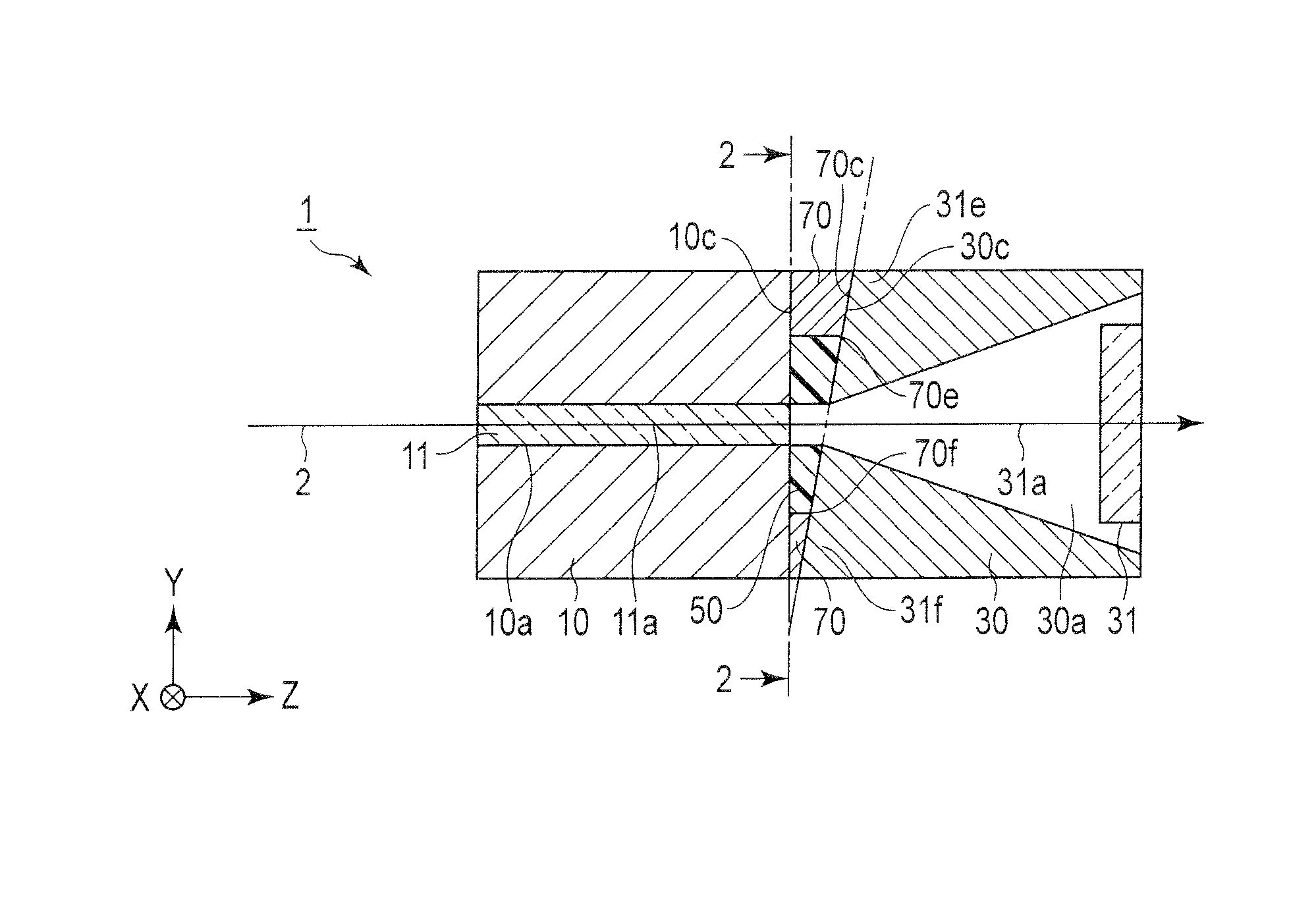
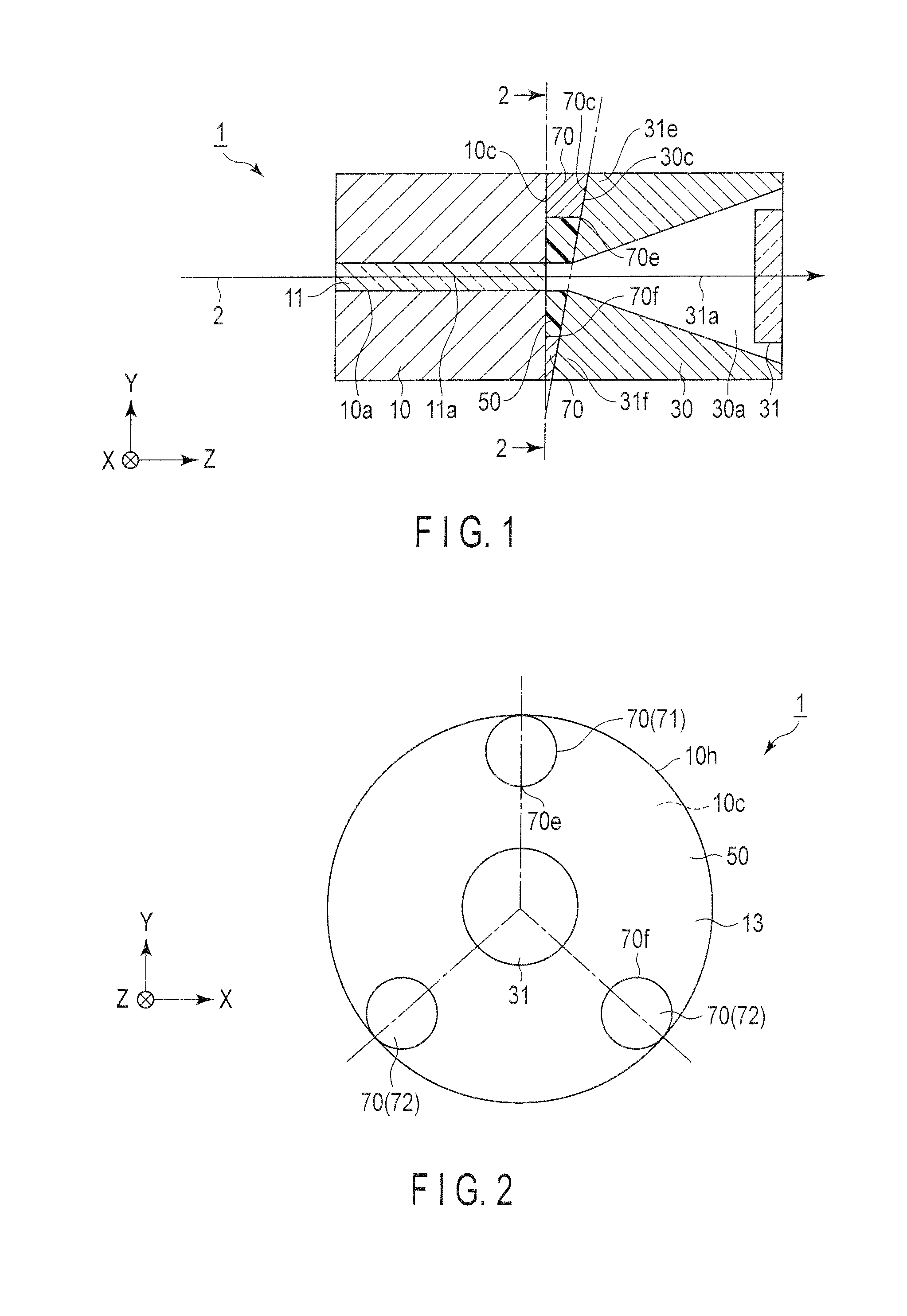
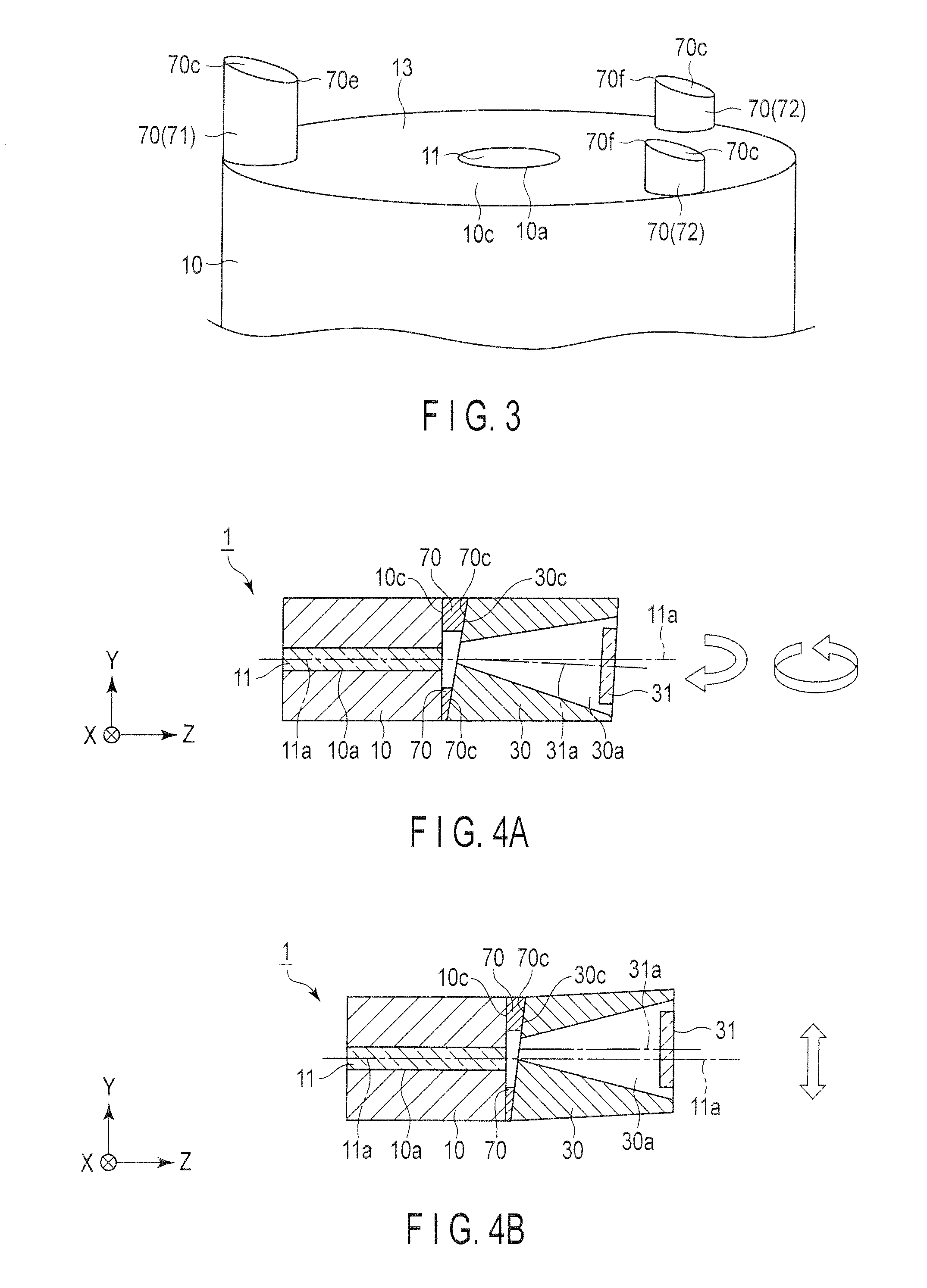
[0029]The first embodiment will be described with reference to FIGS. 1, 2, 3, 4A, 4B, and 4C.

[0030]Note that the direction of an optical axis 11a of an optical fiber 11 will be referred to as a Z-axis direction, the direction perpendicular to the Z-axis direction as an X-axis direction, and the direction perpendicular to the Z- and X-axis directions as a Y-axis direction hereinafter. Note that the Z-axis direction is the direction in which a laser beam 2 emits or transmits through the optical fiber 11 and a phosphor 31. Note that optical coupling indicates coupling of the optical fiber 11 and the phosphor 31 after the positions of an optical fiber holder 10 and a phosphor holder 30 are adjusted to make the optical axis 11a of the optical fiber 11 match an optical axis 31a of the phosphor 31.

[0031]An illumination device 1 includes the optical fiber holder 10 that ...


PUM

PropertyMeasurementUnit
angleaaaaaaaaaa
optical axisaaaaaaaaaa
heightsaaaaaaaaaa

Abstract

An illumination device includes an optical fiber holder configured to hold an optical fiber, a phosphor holder configured to hold a phosphor and faces the optical fiber holder, and a bonding material configured to intervene between the optical fiber holder and the phosphor holder to bond them. The illumination device includes adjustment guide members configured to intervene between the optical fiber holder and the phosphor holder, relatively positionally adjust the optical fiber holder and the phosphor holder so as to arrange an optical axis of the optical fiber and an optical axis of the phosphor on one line, and configured to prevent the optical fiber holder and the phosphor holder from tilting when the bonding material is cured.

Description

CROSS-REFERENCE TO RELATED APPLICATIONS[0001]This application is based upon and claims the benefit of priority from prior Japanese Patent Application No. 2010-167404, filed Jul. 26, 2010, the entire contents of which are incorporated herein by reference.BACKGROUND OF THE INVENTION[0002]1. Field of the Invention[0003]The present invention relates to an illumination device and a method of implementing an illumination device in which one holder and the other holder, each holding an optical element, are bonded after their positions are relatively adjusted while measuring the amount of light so as to minimize the amount of light loss which occurs upon optically coupling the optical elements to each other.[0004]2. Description of the Related Art[0005]The technique of relatively aligning a pair of optical elements including an optical fiber and a phosphor while making their optical axes match each other is generally called “active alignment”. In this active alignment, the amount of light tr...

Claims


Application Information

Patent Timeline
Patent Type & Authority Patents(United States)
IPC IPC(8): G02B6/36G02B6/00
CPCG02B6/0003G02B6/0008
Inventor KUBOI, TORUOHARA, SATOSHI
Owner OLYMPUS CORP
Learn More