Optical coupling element and optical coupling unit

a technology of optical coupling and optical coupling elements, which is applied in the field of optical coupling elements and optical coupling units, can solve the problems of high cost and difficult to perform the molding process stably, and achieve the effect of convenient formation

Active Publication Date: 2009-02-10
ALPS ALPINE CO LTD
View PDF4 Cites 0 Cited by
  • Summary
  • Abstract
  • Description
  • Claims
  • Application Information

AI Technical Summary

Benefits of technology

[0008]The present invention provides an optical coupling element that is constituted by a single component and can be formed readily by molding, and an optical coupling unit equipped with such an optical coupling element.
[0009]An optical coupling element according to the present invention is disposed between an optical fiber and an optical element that face each other and optically couples the optical fiber and the optical element. The optical coupling element includes a substantially cylindrical optical coupling portion whose opposite end surfaces respectively face the optical fiber and the optical element; and a projection projecting from a periphery of the optical coupling portion in a radial direction, the projection being located closer towards one of the opposite end surfaces with respect to a center position between the opposite end surfaces. A diameter of the optical coupling portion at a position corresponding to a first end surface of the projection is substantially equal to a diameter of the optical coupling portion at a position corresponding to a second end surface of the projection. The periphery of the optical coupling portion includes periphery surfaces that are tapered from the positions corresponding to the first and second end surfaces of the projection respectively towards the opposite end surfaces of the optical coupling portion. Accordingly, the optical coupling element can allow for light propagation without requiring a multilayer structure, and the amount of light loss caused by the projection required for fixation purpose can be minimized. In addition, since the optical coupling portion has tapered periphery surfaces, the optical coupling element can have good mold release properties at the time of the molding process, thereby facilitating the molding process.
[0010]In the optical coupling element according to the present invention, the optical coupling portion and the projection are preferably formed from a single resin material. Accordingly, the optical coupling element can be manufactured readily at low cost.

Problems solved by technology

However, since optical coupling elements having such structures are formed by joining together two different components, such optical coupling elements are problematic in view of high costs.
On the other hand, if an optical coupling element is to be formed by resin molding, it is difficult to perform the molding process stably since the optical coupling element has a linear form.

Method used


Image

  • Optical coupling element and optical coupling unit
  • Optical coupling element and optical coupling unit
  • Optical coupling element and optical coupling unit

Examples


Embodiment Construction

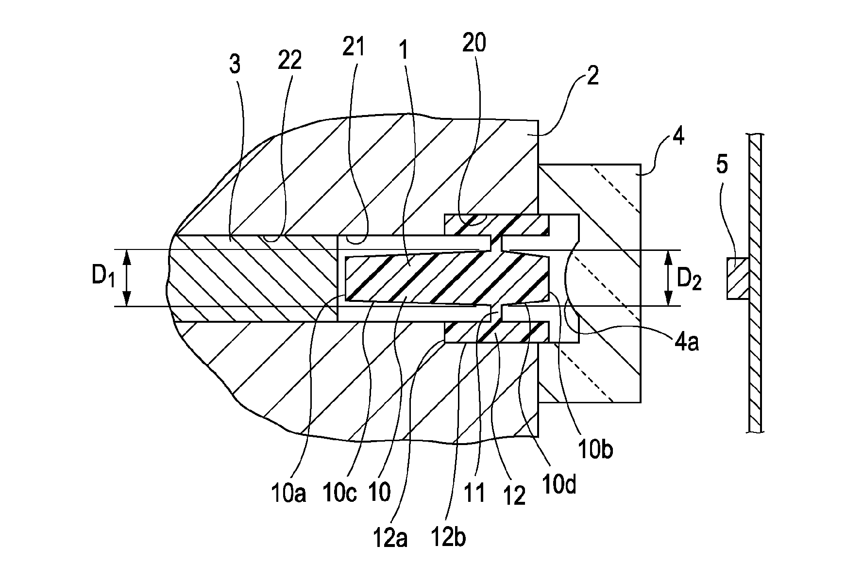
[0020]Embodiments of the present invention will now be described in detail with reference to the drawings. A first embodiment of the present invention will be described first. FIG. 1 is a cross-sectional view of an optical coupling unit according to the first embodiment. As shown in FIG. 1, the optical coupling unit according to the first embodiment includes an optical coupling element 1 that is held by a holding member 2, a lens member 4 having a lens portion 4a and fixed to a first end of the optical coupling element 1, an optical fiber 3 disposed adjacent to a second end of the optical coupling element 1, and a light emitting / receiving portion 5 disposed facing the first end of the optical coupling element 1 across the lens portion 4a.

[0021]The optical coupling element 1 is formed integrally using a single resin material. The optical coupling element 1 is disposed between the optical fiber 3 and the light emitting / receiving portion 5, and has a function for optically coupling th...


PUM


Abstract

An optical coupling element disposed between an optical fiber and an optical element that face each other and optically coupling these two facing components includes a substantially cylindrical optical coupling portion whose opposite end surfaces respectively face the optical fiber and the optical element; and a projection projecting radially from a periphery of the optical coupling portion and being located closer towards one of the opposite end surfaces with respect to a center position therebetween. A diameter of the optical coupling portion at a position corresponding to a first end surface of the projection is substantially equal to a diameter of the optical coupling portion at a position corresponding to a second end surface of the projection. The periphery of the optical coupling portion includes periphery surfaces tapered from the positions corresponding to the first and second end surfaces of the projection respectively towards the opposite end surfaces.

Description

CLAIM OF PRIORITY[0001]This application claims benefit of the Japanese Patent Application No. 2007-127575 filed on May 14, 2007, which is hereby incorporated by reference.BACKGROUND OF THE INVENTION[0002]1. Field of the Invention[0003]The present invention relates to optical coupling elements disposed between an optical fiber and an optical element so as to optically couple the optical fiber and the optical element, and to optical coupling units equipped with such optical coupling elements. In particular, the present invention relates to an optical coupling element and an optical coupling unit in which an optical coupling portion is free of a multilayer structure.[0004]2. Description of the Related Art[0005]Optical coupling elements that optically couple an optical fiber and an optical element, such as a light-emitting element or a light-receiving element, have been known. In addition, optical coupling units that include such an optical coupling element and a holding member that hol...

Claims


Application Information

Patent Timeline
Patent Type & Authority Patents(United States)
IPC IPC(8): G02B6/36
CPCG02B6/4206G02B6/4212G02B6/421
Inventor SONODA, KATSUNARI
Owner ALPS ALPINE CO LTD
Why Eureka
Try Eureka