Drilling tool for chip removing machining as well as a loose top and a basic body therefor

a technology for removing machining and drilling tools, which is applied in the direction of twist drills, manufacturing tools, cutting inserts, etc., can solve the problems of large dimensional accuracy requirements, disadvantageous total manual force required to turn in the loose top to the end position thereof, and high manufacturing-technical natur

Active Publication Date: 2014-07-22
SANDVIK INTELLECTUAL PROPERTY AB
View PDF21 Cites 13 Cited by
  • Summary
  • Abstract
  • Description
  • Claims
  • Application Information

AI Technical Summary

Benefits of technology

[0015]The invention is generally based on the idea of utilizing the limited length of an advantageous compact loose top in a way that is optimal for the transfer of torque at the same time as the means, which are required for provisionally centering the loose top in connection with the turning-in into the jaw, can be integrated in the loose top without unnecessarily being added to its total length. In an embodiment, this is effected by allowing the individual tangential contact surface of the loose top to extend from the rear end thereof to the front one and transform into the side contact surface as well as a guide surface via a recess surface common to the same. In such a way, the guide surfaces necessary for the provisional centering do not need to be located axially behind the tangential contact surfaces.

Problems solved by technology

A disadvantage of the known drilling tool is of a manufacturing-technical nature and includes the fact that the requirements of dimensional accuracy are great.
In other words, the total manual force that is required to turn in the loose top to the end position thereof can become disadvantageously great.
Another disadvantage is that the transfer of torque between the basic body and the loose top is exclusively effected via the comparatively short lugs that protrude rearward from the rear end of the envelope surface of the loose top.
In other words, the tangential support surfaces and the tangential contact surfaces become necessarily small and may cause so high a surface pressure that a risk of deformation damage arises, particularly in the front finger portions of the branches.
A further disadvantage is that the total axial length of the loose top is considerable in relation to the diameter (2:1), more precisely as a consequence of the fact that the front part, along which the envelope surface extends, occupies approximately 50% of the total length, while the remaining 50% is occupied by the rear pin part.
This means that the total volume of the loose top in relation to the diameter becomes large and causes expensive consumption of material in the manufacture.
Yet another disadvantage is that the pinch or grip of the branches on the loose top is limited to the rear half of the loose top, while the front half of the same lacks lateral support.

Method used


Image

  • Drilling tool for chip removing machining as well as a loose top and a basic body therefor
  • Drilling tool for chip removing machining as well as a loose top and a basic body therefor
  • Drilling tool for chip removing machining as well as a loose top and a basic body therefor

Examples


Embodiment Construction

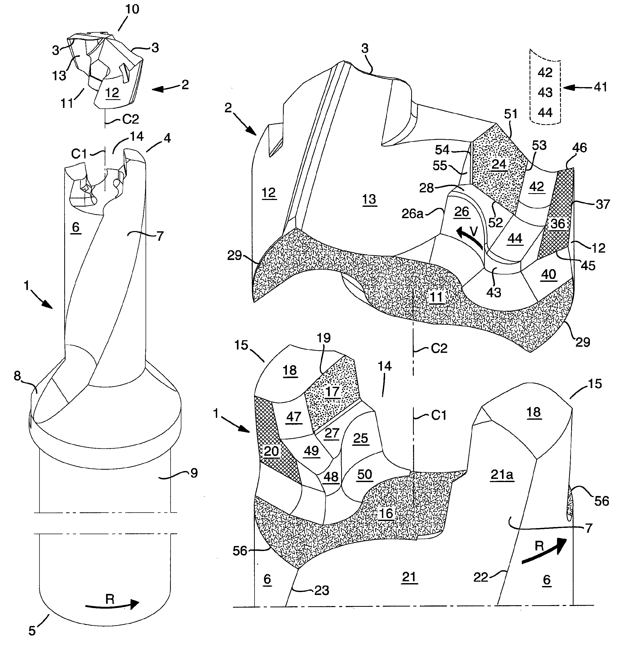
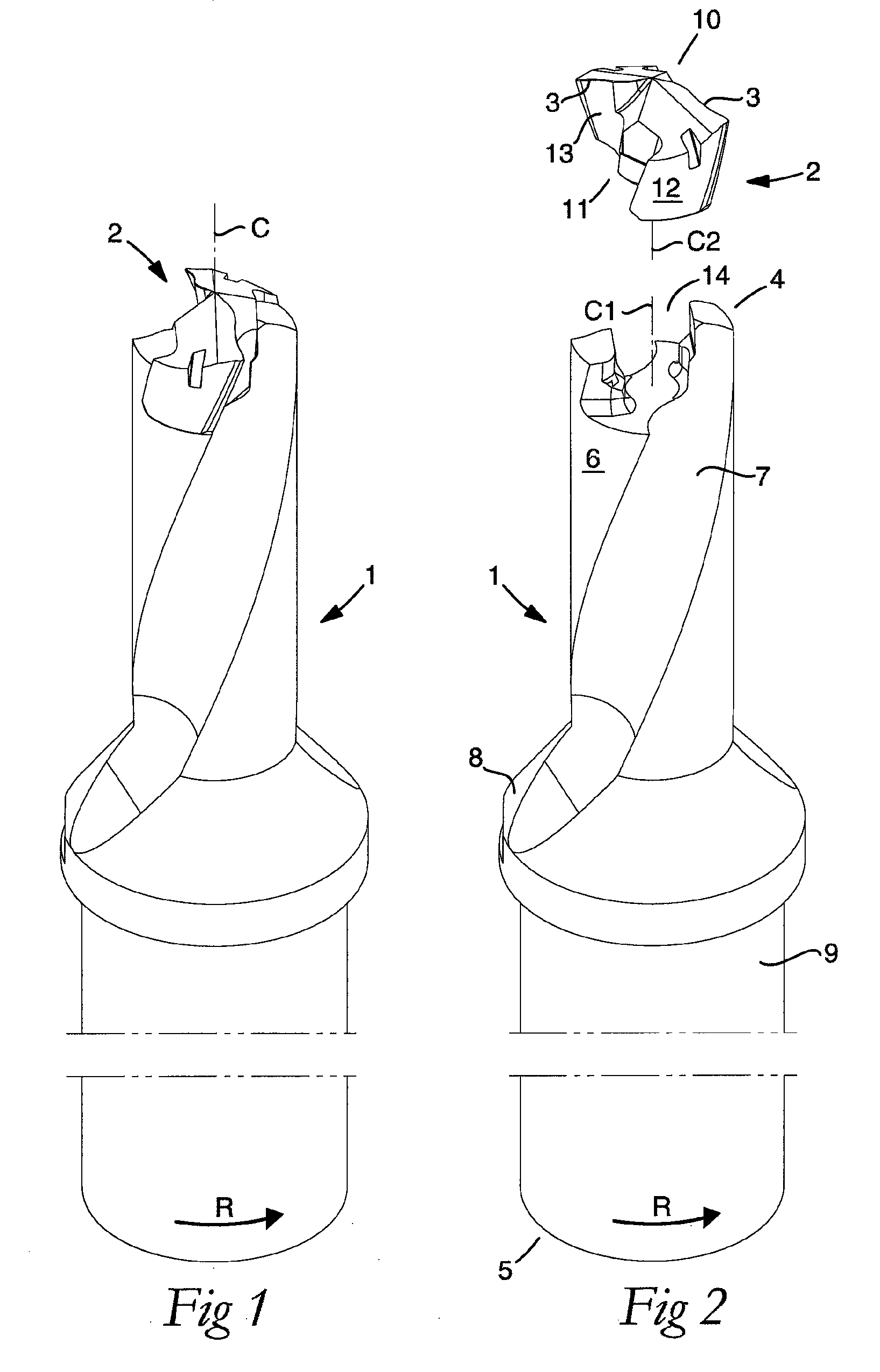
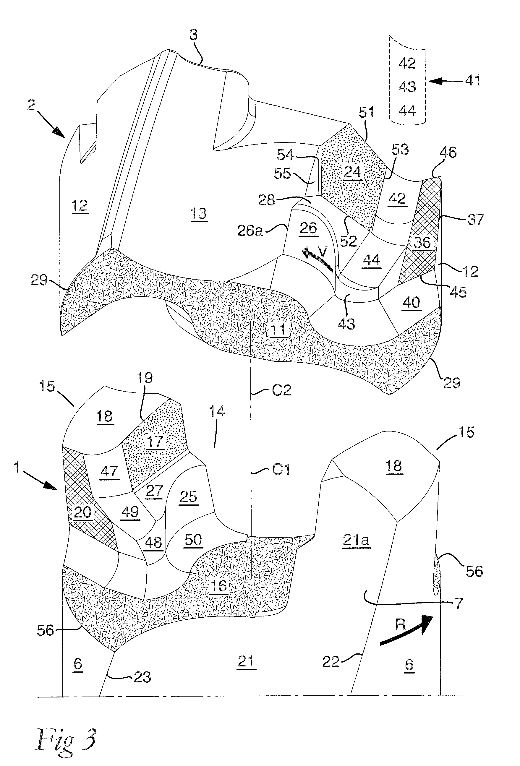
[0030]In the following, a number of co-operating pairs of surfaces of the basic body and the loose top, respectively, will be described. When these surfaces are present on the basic body, the same are denominated “support surfaces”, while the corresponding surfaces of the loose top are denominated “contact surfaces” (e.g., “axial support surface” and “axial contact surface”, respectively). In order to further distinguish different surfaces from each other, there are in addition used such prefixes as “axial” and “tangential” in the expressions axial support surfaces / axial contact surfaces and tangential support surfaces / tangential contact surfaces, respectively. However, these prefixes do not relate to how the different surfaces are geometrically situated in the tool, but rather to the directions in which they transfer and carry forces, respectively. It should also be pointed out that the loose top includes a rear end that in an embodiment is in the form of a plane surface and serves...


PUM

PropertyMeasurementUnit
diameteraaaaaaaaaa
angleaaaaaaaaaa
distanceaaaaaaaaaa

Abstract

A loose top for drilling tools, including front and rear ends, a pair of envelope part surfaces concentric with a center axis, and two chip flutes countersunk in relation to the pair of envelope part surfaces between which two bars project radially from a central core, the front end including a cutting edge and at least one clearance surface positioned rotationally behind the cutting edge, the rear end forming an axial contact surface. The loose top includes two opposite side contact surfaces against which elastically bendable branches of a tool basic body are pressed in use, a pair of convex guide surfaces situated axially behind the side contact surfaces, the guide surfaces being concentric with the center axis and radially spaced-apart from the center axis at a distance that is less than the radial distance between the center axis and a respective side contact surface, and a pair of torque-carrying tangential contact surfaces that are situated radially inside the envelope part surfaces and outside the side contact surfaces. The axial contact surface extends perpendicular to the center axis between borderlines adjacent to the two envelope part surfaces.

Description

[0001]This application claims priority under 35 U.S.C. §119 to Swedish Patent Application No. 0900848-3, filed on Jun. 23, 2009, which is incorporated by reference herein in its entirety.FIELD OF THE INVENTION[0002]The present invention relates generally to a drilling tool for chip removing machining, including a basic body and a loose top. The basic body includes front and rear ends, and an envelope surface that includes two countersunk chip flutes and is concentric with a first center axis around which the basic body is rotatable in a given direction of rotation. The loose top includes front and rear ends, a pair of envelope part surfaces concentric with a second center axis, and two chip flutes countersunk in relation to the pair of envelope part surfaces between which two bars project radially from a central core, the front end including a cutting edge and at least one clearance surface positioned rotationally behind the cutting edge, the rear end forming an axial contact surfac...

Claims


Application Information

Patent Timeline
Patent Type & Authority Patents(United States)
IPC IPC(8): B23D71/00
CPCB23B51/02B23B2205/02B23B2251/02B23C5/22Y10T408/909Y10T408/892Y10T408/9095Y10T408/95Y10T408/9098
Inventor PABEL, HELENA
Owner SANDVIK INTELLECTUAL PROPERTY AB
Why Eureka
Try Eureka