Fuel cell stack with water drainage structure

a fuel cell and stack technology, applied in the direction of fuel cells, electrical equipment, electrochemical generators, etc., can solve the problems of rapid repetitive increase and decrease in cell voltage, deterioration of mea catalysts, and ineffective removal of water by methods

Active Publication Date: 2014-07-22
HYUNDAI MOTOR CO LTD +1
View PDF8 Cites 5 Cited by
  • Summary
  • Abstract
  • Description
  • Claims
  • Application Information

AI Technical Summary

Benefits of technology

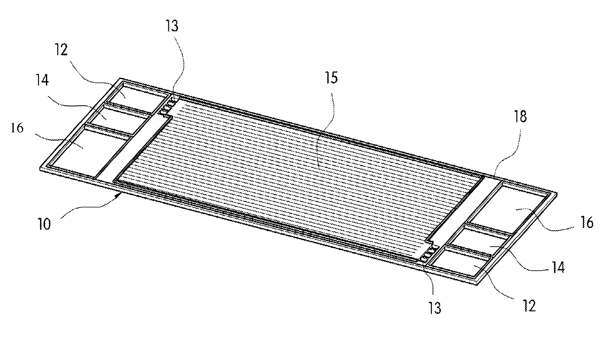
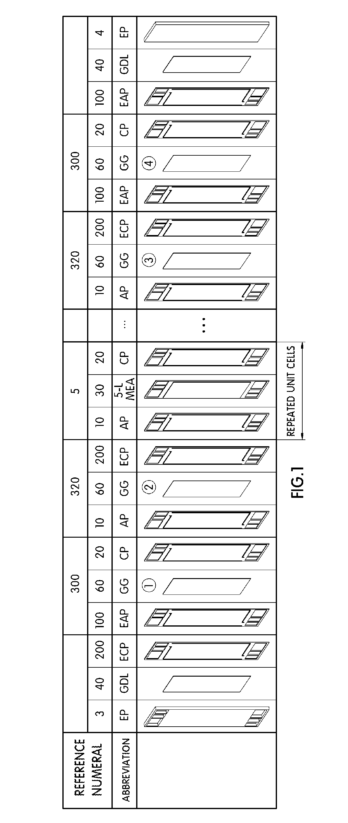
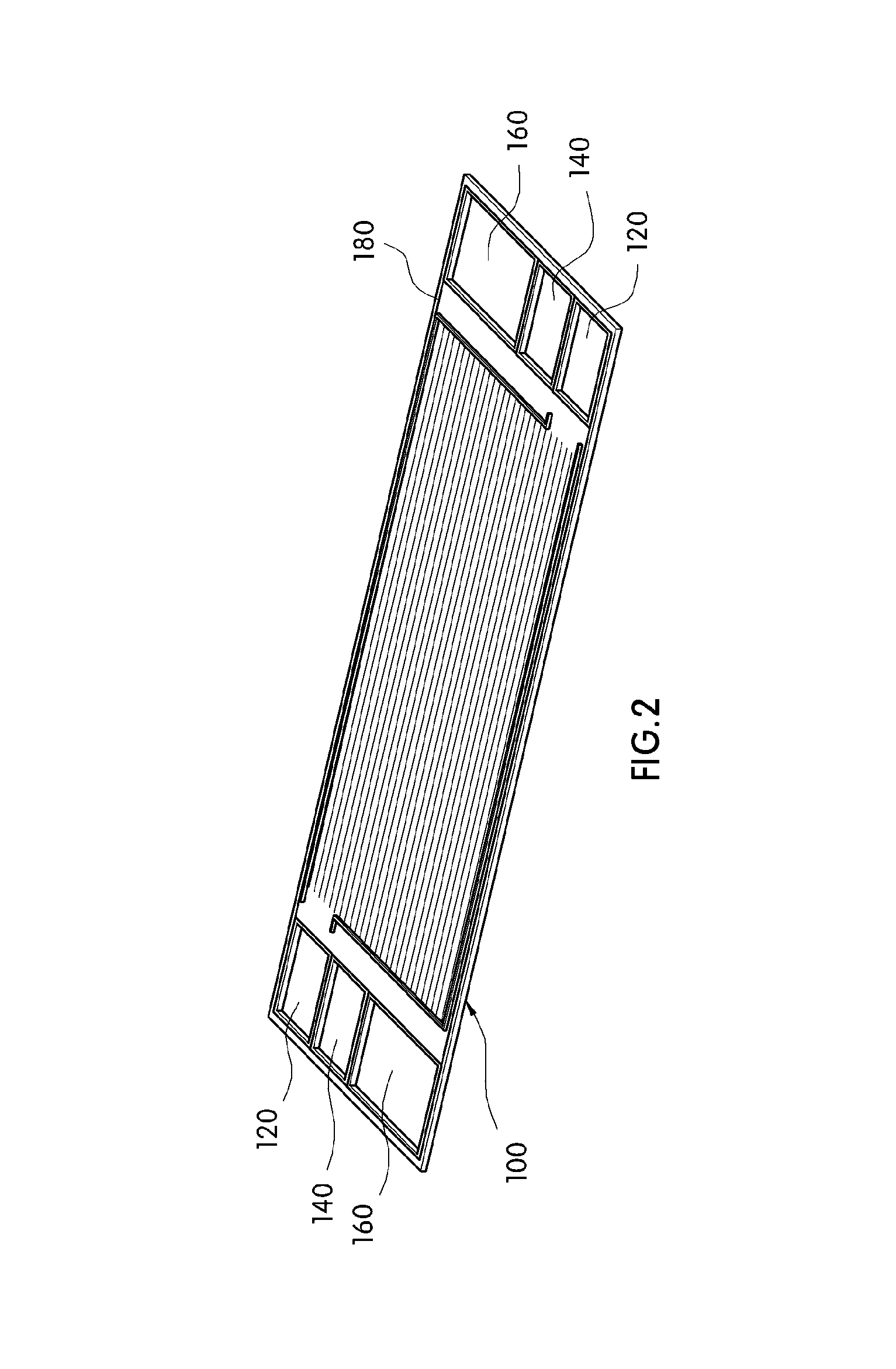
[0019]The present invention provides a fuel cell stack having a water drainage structure, which can effectively drain condensed water and prevent water from flowing into unit cells by forming the same structure as an existing unit cell of the fuel cell stack and positioning the structure at an end cell portion of the fuel cell stack.

Problems solved by technology

In this case, the water flows into the outermost unit cells that are in contact with the open EP 3 to cause a rapid repetitive increase and decrease in cell voltage and a deterioration of MEA catalyst due to the presence of a large amount of water in the unit cells, which may specifically be a serious problem in the anode loop as it is a closed loop.
However, this method does not remove the water as effectively as the industry would hope.
However, according to the above-described configuration, the bypass plate and the intermediate plate should be separately developed and added to the fuel cell stack, and thus the overall configuration of the fuel cell stack is further complicated when this method is utilized thereby indirectly increasing the overall costs of production.

Method used


Image

  • Fuel cell stack with water drainage structure
  • Fuel cell stack with water drainage structure
  • Fuel cell stack with water drainage structure

Examples


Embodiment Construction

[0038]Hereinafter reference will now be made in detail to various embodiments of the present invention, examples of which are illustrated in the accompanying drawings and described below. While the invention will be described in conjunction with exemplary embodiments, it will be understood that present description is not intended to limit the invention to those exemplary embodiments. On the contrary, the invention is intended to cover not only the exemplary embodiments, but also various alternatives, modifications, equivalents and other embodiments, which may be included within the spirit and scope of the invention as defined by the appended claims.

[0039]It is understood that the term “vehicle” or “vehicular” or other similar term as used herein is inclusive of motor vehicles in general such as passenger automobiles including sports utility vehicles (SUV), buses, trucks, various commercial vehicles, watercraft including a variety of boats and ships, aircraft, and the like, and inclu...


PUM

PropertyMeasurementUnit
chemical energyaaaaaaaaaa
electrical energyaaaaaaaaaa
bonding pressureaaaaaaaaaa

Abstract

The present invention provides a fuel cell stack with a water drainage structure, which can effectively drain condensed water and prevent water from flowing into unit cells by combining an end anode plate (EAP) and an end cathode plate (ECP), which are formed by modifying an anode plate (AP) and cathode plate (CP) respectively. In doing so, the modified anode plate (AP) and cathode plate (CP) are converted into a dummy cell which is positioned at the end portions of the fuel cell stack.

Description

CROSS-REFERENCE TO RELATED APPLICATION[0001]This application claims under 35 U.S.C. §119(a) the benefit of Korean Patent Application No. 10-2010-0114180 filed Nov. 17, 2010, the entire contents of which are incorporated herein by reference.BACKGROUND[0002](a) Technical Field[0003]The present invention relates to a fuel cell stack having a water drainage structure. More particularly, it relates to a fuel cell stack having a water drainage structure, which can effectively drain condensed water and prevent water from flowing into unit cells by combining an end anode plate (EAP) and an end cathode plate (ECP), which are formed by modifying an existing anode plate (AP) and cathode plate (CP) respectively into a dummy cell, and positioning the dummy cell at an end cell portion.[0004](b) Background Art[0005]A fuel cell is an electricity generation system that electrochemically converts the chemical energy directly into electrical energy in a fuel cell stack instead of converting chemical e...

Claims


Application Information

Patent Timeline
Patent Type & Authority Patents(United States)
IPC IPC(8): H01M8/06
CPCH01M8/04156H01M8/2465H01M2008/1095Y02E60/50H01M8/2483
Inventor YANG, YOO CHANGKIM, JONG SUNGKIM, SAE HOONJIN, SANG MUNBAECK, SUK MINHEO, SEONG IL
Owner HYUNDAI MOTOR CO LTD
Why Eureka
Try Eureka