Constant frequency synthetic ripple power converter

a power converter and constant frequency technology, applied in the field of power converters, can solve the problems of jitter or phase noise of switching, the most difficult transition, and the circuit is often affected, and achieve the effect of converting from dcm mode into ccm very quickly

Active Publication Date: 2014-07-22
QUALCOMM INC
View PDF16 Cites 10 Cited by
  • Summary
  • Abstract
  • Description
  • Claims
  • Application Information

AI Technical Summary

Benefits of technology

[0024]It is an objective of the present invention to provide a switching power converter that combines the main advantages of the hysteretic control with synthetic ripple signal generation with the advantages of operating at constant frequency in CCM and inherently stable in all conditions. The converter can be switched from DCM mode into CCM very quickly without affecting significantly the regulated output voltage.
[0025]It is another objective of the present invention to provide an alternative to the current use of frequency control circuits, for instance PLL (Phase Lock Loop) circuits, to synchronize the switching power converter to the desired switching frequency, therefore consuming low power thus contributing to the overall efficiency of the power converter.
[0026]It is another objective of the present invention to provide a means for operating a boost converter at very high switching frequencies while maintaining the stability of the system in all conditions. It is a further objective of the present invention to provide a means for controlling the gain of the system.

Problems solved by technology

Furthermore these circuits are often affected by noise and present jitter or phase noise of the switching.
In hysteretic power converters one of the most challenging transitions occurs when the load is abruptly switched on from a very light load to a heavy load condition.
However, the stability of this system is very difficult to study and, more importantly, to control.
The gain of the system can at times be too high to guarantee a stable operation in all conditions.
Although the ramp signal may be at a constant frequency and although the power converter may switch at a constant frequency in Continuous Conduction Mode (CCM) in specific conditions, it does not maintain the desired switching frequency in all conditions.
Furthermore the output of the converter is subject to switching noise that could be even greater in amplitude than the superimposed voltage ripple and therefore the control of the converter may be very difficult to obtain even if the amplitude of the ramp in the reference voltage is large.
Lastly the operation is not necessarily stable and, in fact Lipcsei introduces a not well defined stability circuit in the loop without teaching how that would function, but certainly the possibility for instability and sub-harmonics operation is quite high.
The ramp signal representative of the synthetic ripple signal is not a constant frequency ramp, therefore while this approach may be interesting because it may show a stable system with fast load transient response, it certainly does not teach how to obtain a high performing constant frequency switching power converter.

Method used


Image

  • Constant frequency synthetic ripple power converter
  • Constant frequency synthetic ripple power converter
  • Constant frequency synthetic ripple power converter

Examples


Embodiment Construction
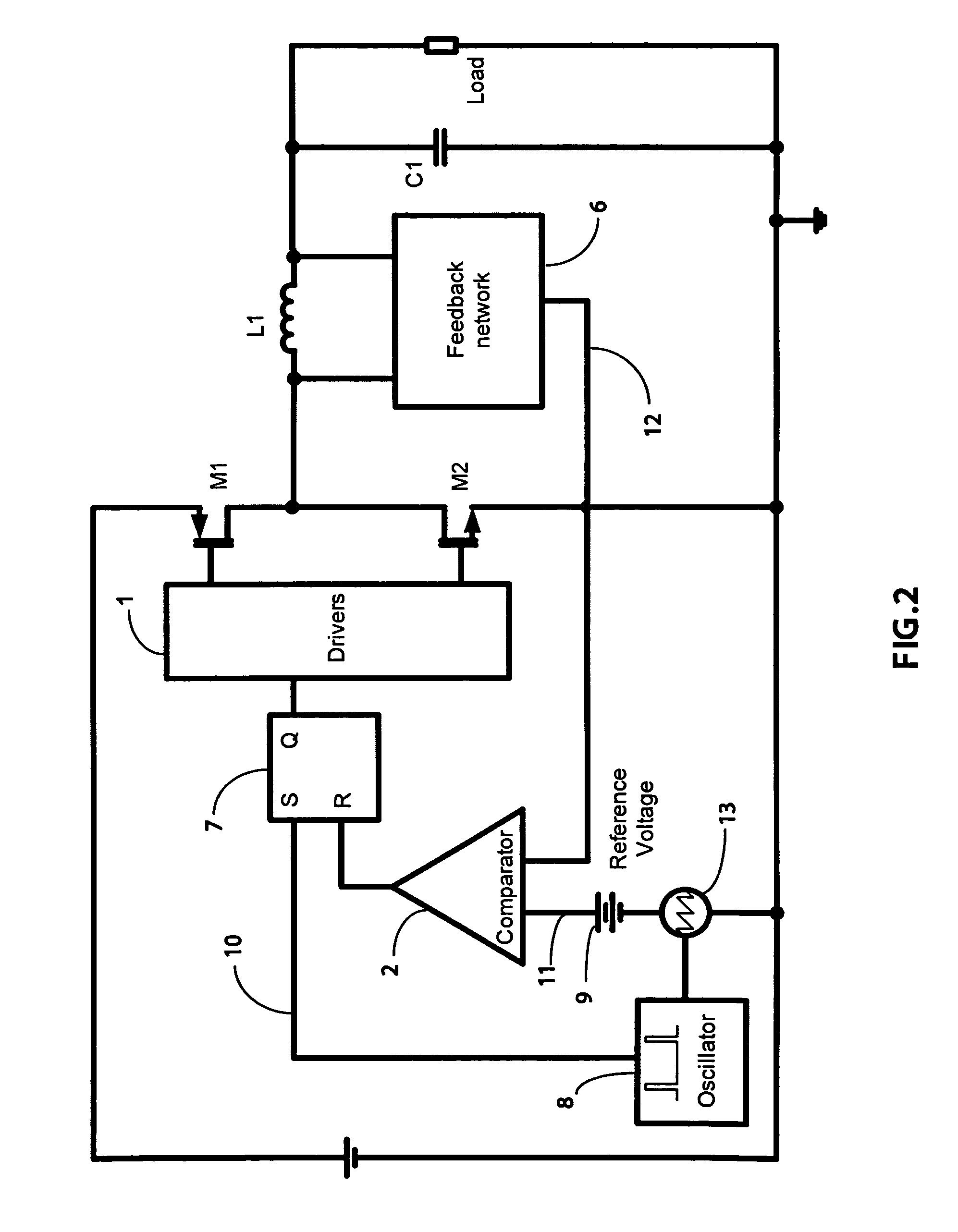
[0077]A FIG. 2

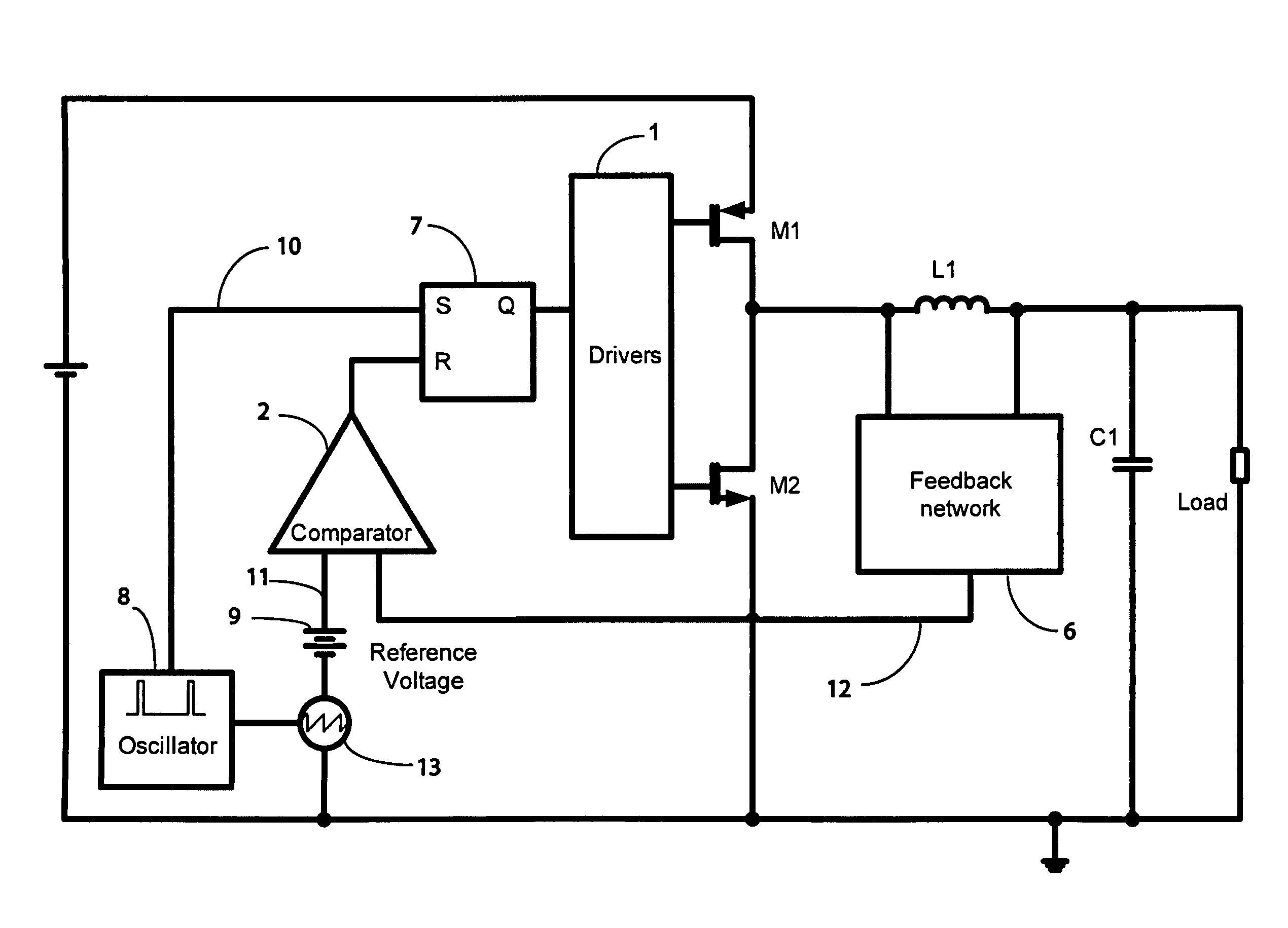
[0078]FIG. 2 shows the block diagram of the power converter according to the preferred embodiment of the present invention for a buck converter. The oscillator 8 generates a clock signal with a very small duty cycle to generate the ramp signal 13 and to synchronize the converter with the minimum off-time. The clock signal could also be generated externally to the power converter integrated circuit to synchronize the system to any desired frequency. The ramp signal generator 13 generates the saw tooth waveform (but it could as well generate a different shape ramp signal) synchronized to the clock signal 10. The ramp signal is in series to a reference voltage 9 (typically a bandgap reference voltage or any other DC voltage).

[0079]The resulting signal 11 feeds the comparator 2 that compares it with the synthetic ripple signal 12 coming from the feedback network 6. The feedback network 6 has the task to generate a ripple signal of the right amplitude and of the right bandw...


PUM


Abstract

A novel method to operate synthetic ripple switching power converters at constant frequency is presented. The method includes the generation of a clock signal and the summing of a ramp signal to a DC voltage reference to be compared to a synthetic ripple signal. The ramp signal is synchronous with the clock signal. A minimum on-time or minimum off-time type of control is implemented. The switching frequency is constant.The presented approach provides significant advantages with respect to the more traditional means of utilizing hysteretic approaches combined with frequency control circuits.The switching frequency can be as high as the one obtained for a hysteretic power converter, the load and line transient response is comparable with or better than the one achieved with hysteretic approaches. The stability is obtained by adapting the slope of the ramp signal in order to obtain the adequate gain of the system.The method is presented for buck and boost hysteretic high frequency switching power converters, but can be utilized also for buck-boost converters. The general method can be utilized also for multiphase switching power converters.A non clocked variant of the novel circuit topology is also presented to improve load and line transient performance.

Description

BACKGROUND OF THE INVENTION[0001]1. Field of the Invention[0002]The present invention is in the field of power converters. The present invention is further in the field of semiconductor switching power converters. The present invention further relates to the field of integrated synthetic ripple control methods for switching power converters and circuits. The present invention is further in the field of integrated switching power converters. The present invention is further in the field of minimum on- and off-time control types for switching power converters. The implementation is not limited to a specific technology, and applies to either the invention as an individual component or to inclusion of the present invention within larger systems which may be combined into larger integrated circuits.[0003]2. Brief Description of Related Art[0004]Modern electronic applications require power management devices that supply power to integrated circuits or more generally to complex loads. In g...

Claims


Application Information

Patent Timeline
Patent Type & Authority Patents(United States)
IPC IPC(8): G05F1/00H02M1/00H02M3/156
CPCH02M3/156H02M2001/0025H02M1/0025
Inventor MENEGOLI, PAOLOMARINO, FABIO ALESSIO
Owner QUALCOMM INC
Why Eureka
Try Eureka