Method for moving an aircraft along the ground

a technology for moving aircraft and ground, applied in the direction of vehicle position/course/altitude control, process and machine control, instruments, etc., can solve the problems of not always being possible, and achieve the effect of simplifying the movement of aircra

Active Publication Date: 2014-07-22
AIRBUS SAS +1
View PDF69 Cites 4 Cited by
  • Summary
  • Abstract
  • Description
  • Claims
  • Application Information

AI Technical Summary

Benefits of technology

[0007]Moving the aircraft by means of at least two appliances therefore offers greater flexibility for maneuvering the aircraft. There are more movement possibilities and the aircraft can now make tight turns and even make a 180° turn on the spot. It therefore becomes possible to maneuver an aircraft, even one of large dimensions, on most runways or taxiways, which is not always currently possible. In addition, use of at least two appliances reduces the stresses on each part of the aircraft (such as the landing gear) to which they are connected, by distributing these stresses, as compared with connection to a single landing gear. Moreover, if one of the two appliances breaks down during the maneuver, the other appliance can continue all or part of the maneuver. Lastly, although tractors are currently qualified for a given aircraft so that their dimensions are compatible with that of the aircraft, use of at least two appliances could reduce, or even eliminate, this constraint. The number of different types of appliance required on a given airport platform is therefore reduced.
[0050]Advantageously, the appliance can detect presence of an aircraft landing gear in a predetermined zone away from the appliance and, further to this detection, take up a position where it can move the aircraft.

Problems solved by technology

It therefore becomes possible to maneuver an aircraft, even one of large dimensions, on most runways or taxiways, which is not always currently possible.

Method used


Image

  • Method for moving an aircraft along the ground
  • Method for moving an aircraft along the ground
  • Method for moving an aircraft along the ground

Examples


Embodiment Construction

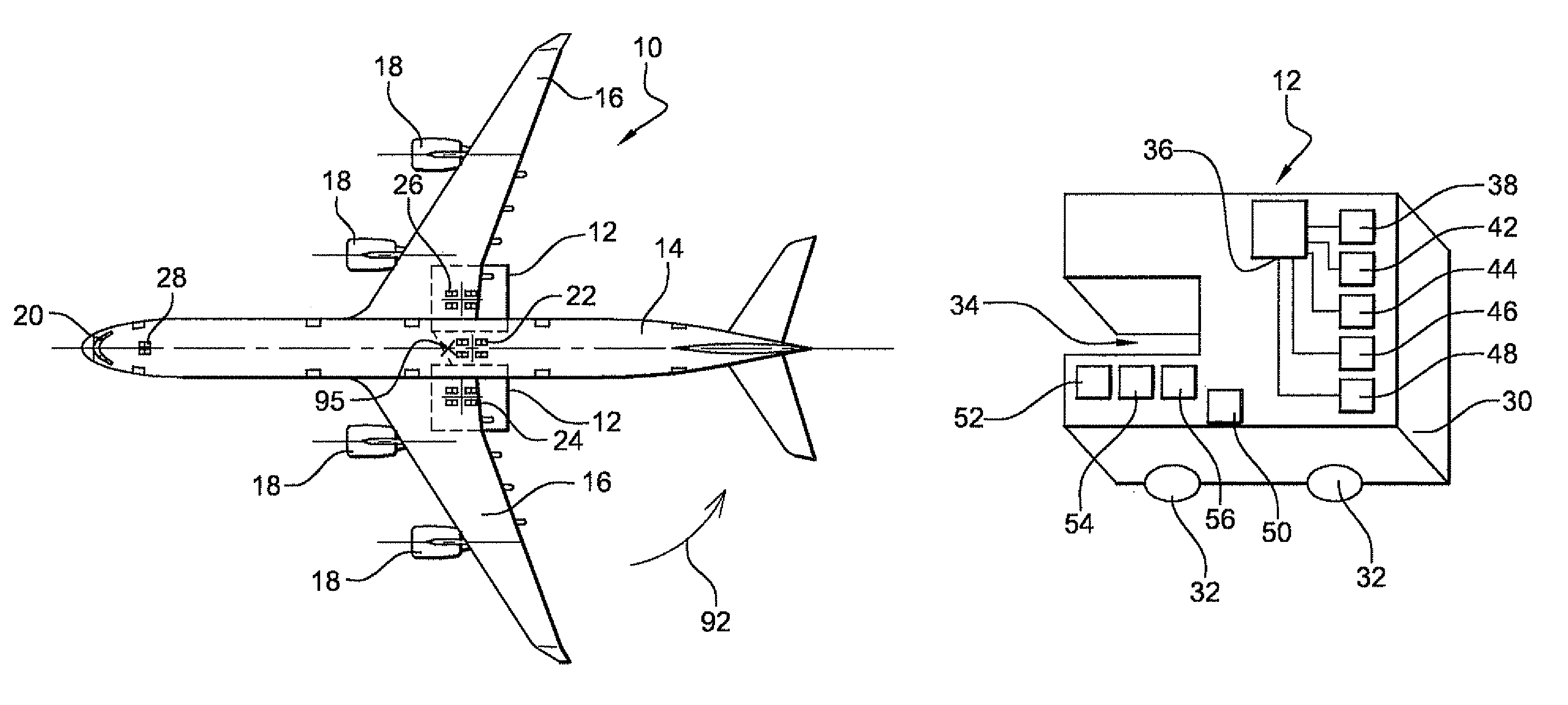
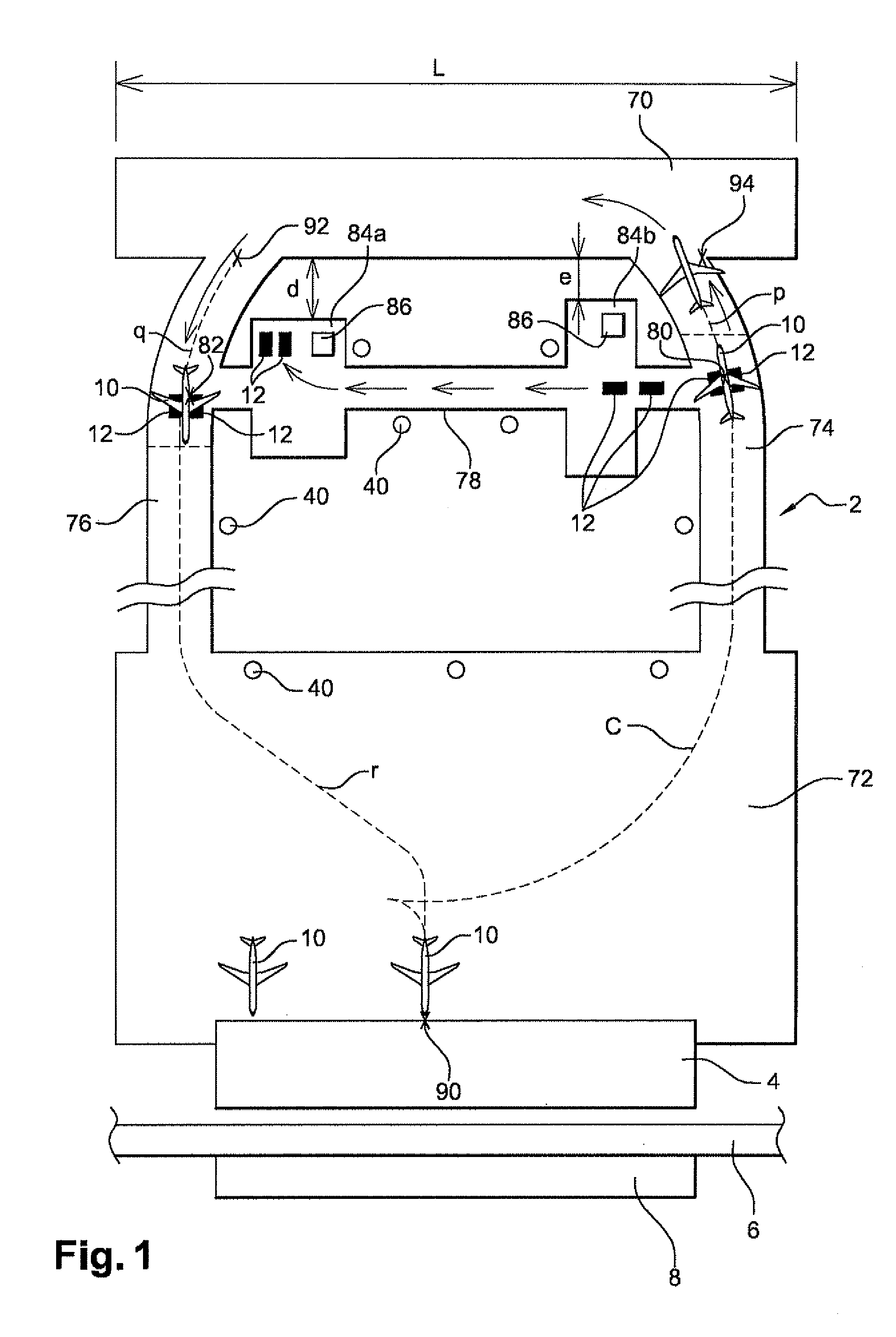
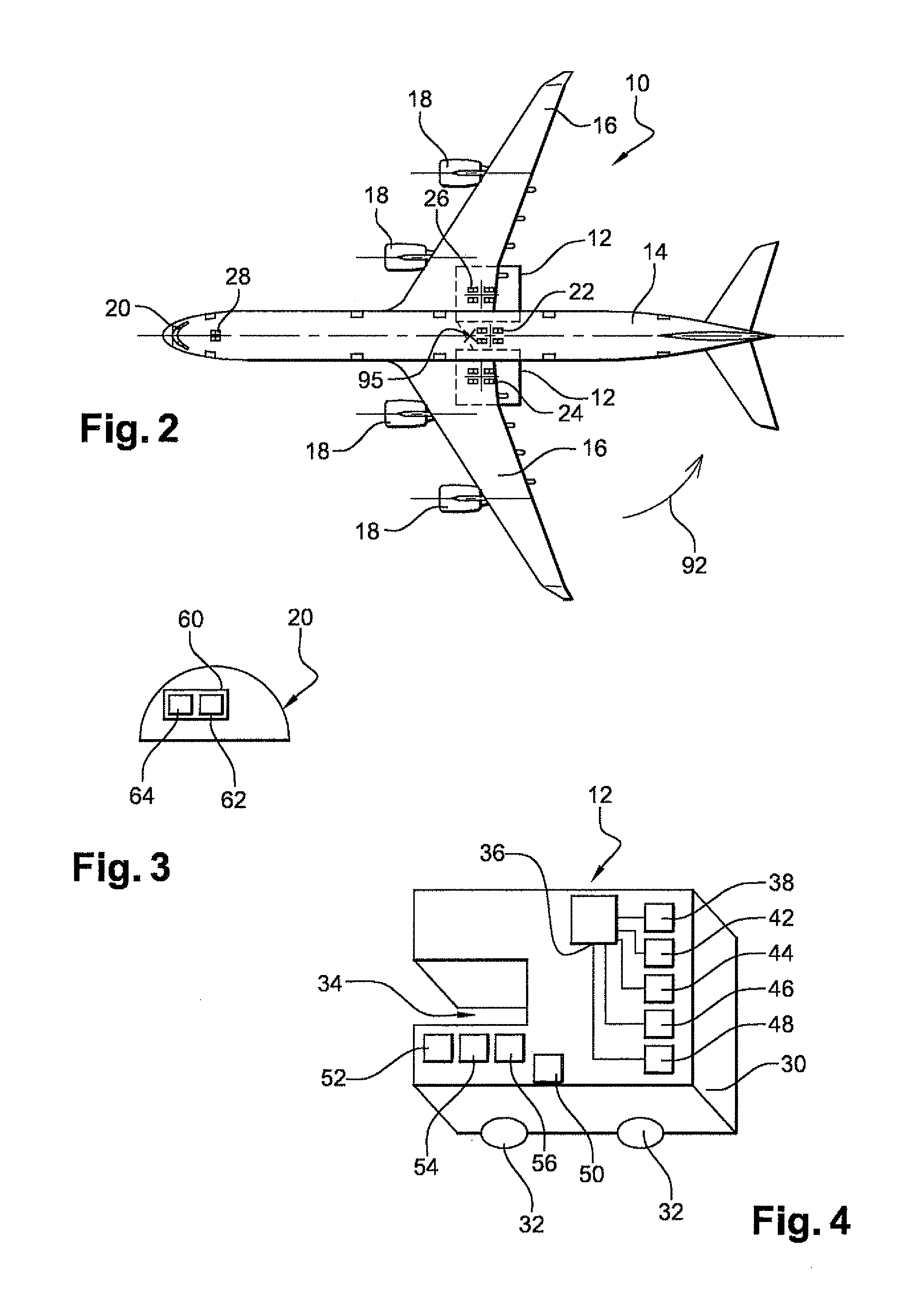
[0071]FIG. 1 shows an airport zone 2 invention is implemented. This zone 2 comprises for example an air terminal 4 for passenger in which the access to aircraft which in this case are intended for commercial service. Passengers can access the air terminal from outside the airport zone via a road 6, a car park 8 being provided to park road automotive vehicles near zone 2. Zone 2 shows aircraft 10 which in this case are aircraft like that illustrated at larger scale on FIG. 2. The airport zone 2 also shows appliances 12 like that illustrated on FIG. 4.

[0072]The aircraft 10, used to implement the invention, comprise for example, as illustrated on FIG. 2, a fuselage 14, two wings 16, and one or more engines 18. The aircraft illustrated therefore comprises four reactors 18 forming the engines. An aircraft cockpit 10 is installed at the front of the fuselage. The aircraft comprises several main landing gears. In this case, they are the central 22, left 24 and right 26 landing gears placed...


PUM


Abstract

The invention relates to a method according to which an aircraft (10) is moved along the ground by means of at least two separate appliances (12) connected to the aircraft independently from each other or other appliances.A control element is provided for moving an aircraft, said element sending instructions to at least two separate appliances in order to move the aircraft along the ground by means of the appliances.The invention also relates to an appliance (12) for implementing the method according to the invention, which can communicate with an identical appliance in order to transmit and / or receive at least one datum relating to a position and / or a movement of one of the appliances.

Description

FIELD OF THE INVENTION[0001]The invention relates to moving aircraft along the ground, in particular before take-off and after landing.BACKGROUND OF THE INVENTION[0002]An aircraft frequently needs to reverse to leave its parking point. However, its engines cannot generally accomplish this movement independently. A known method is therefore to push the aircraft using a tractor from its parking point, reversing it to a position from which it can move independently using its engines alone. This operation is usually called “pushback”. Systems used to tow aircraft along the ground are for example described in documents U.S. Pat. Nos. 3,025,922, 3,015,509 and 3,005,510. The tractor is controlled by a pilot onboard the appliance or controlling the appliance remotely. The tractor is generally connected to the nose landing gear of the aircraft in order to move it.[0003]However, the nose landing gear is not originally designed for this type of operation. The stresses generated in the landing ...

Claims


Application Information

Patent Timeline
Patent Type & Authority Patents(United States)
IPC IPC(8): G05D1/00
CPCB64F1/22B64F1/227B64F1/228Y02T50/826Y02T50/80
Inventor FRINGS, CARSTENCROS, CHRISTOPHE
Owner AIRBUS SAS
Why Eureka
Try Eureka